Multiple chamber airbags and methods

a multi-chamber, airbag technology, applied in the direction of pedestrian/occupant safety arrangement, vehicular safety arrangment, vehicle components, etc., can solve the problems of high cost of airbag fabric production, labor-intensive cutting and sewing operations, and more complex configuration

Inactive Publication Date: 2003-02-20
MILLIKEN & CO
View PDF20 Cites 97 Cited by
  • Summary
  • Abstract
  • Description
  • Claims
  • Application Information

AI Technical Summary

Benefits of technology

[0016] To achieve these and other objects and in accordance with the purpose of the invention, as embodied and broadly described herein, the present invention provides an airbag cushion having at least one fabric component, and wherein said airbag cushion possesses an effective fabric usage factor of less than about 0.095. The effective fabric usage factor is derived from an effective fabric usage index which concerns (and is defined as) the quotient of the total amount of fabric utilized to manufacture the airbag cushion (measured in square meters) over the total volume of available inflation airspace within the airbag cushion (measured in liters). In order to exhibit a sufficiently low effective fabric usage factor, the amount of fabric must be very low with a correspondingly high available inflation airspace volume. Of course, this airspace volume will be the same for each factor since the measurements of both factors (seam usage and fabric usage) are made for the same bag. Such an airbag cushion may comprise at least two separate fabric panels or a single panel with portions which require connection. The inventive bag is able to provide high available inflation airspace volumes due to the particular configurations of the used fabric panels or portions. The preferred configurations permit more efficient utilization of fabric webs by cutting panels from the webs and producing less waste of unused fabric. The preferred embodiment is discussed in greater detail below.

Problems solved by technology

Inflatable protective cushions used in passenger vehicles are a component of relatively complex passive restraint systems.
Inflatable cushions for use in the protection of passengers against frontal or side impacts must generally have a more complex configuration since the position of a vehicle passenger may not be well defined and greater distance may exist between the passenger and the surface of the vehicle against which that passenger might be thrown in the event of a collision.
However, a problem still resides in the need for labor-intensive cutting and sewing operations for large-scale manufacture.
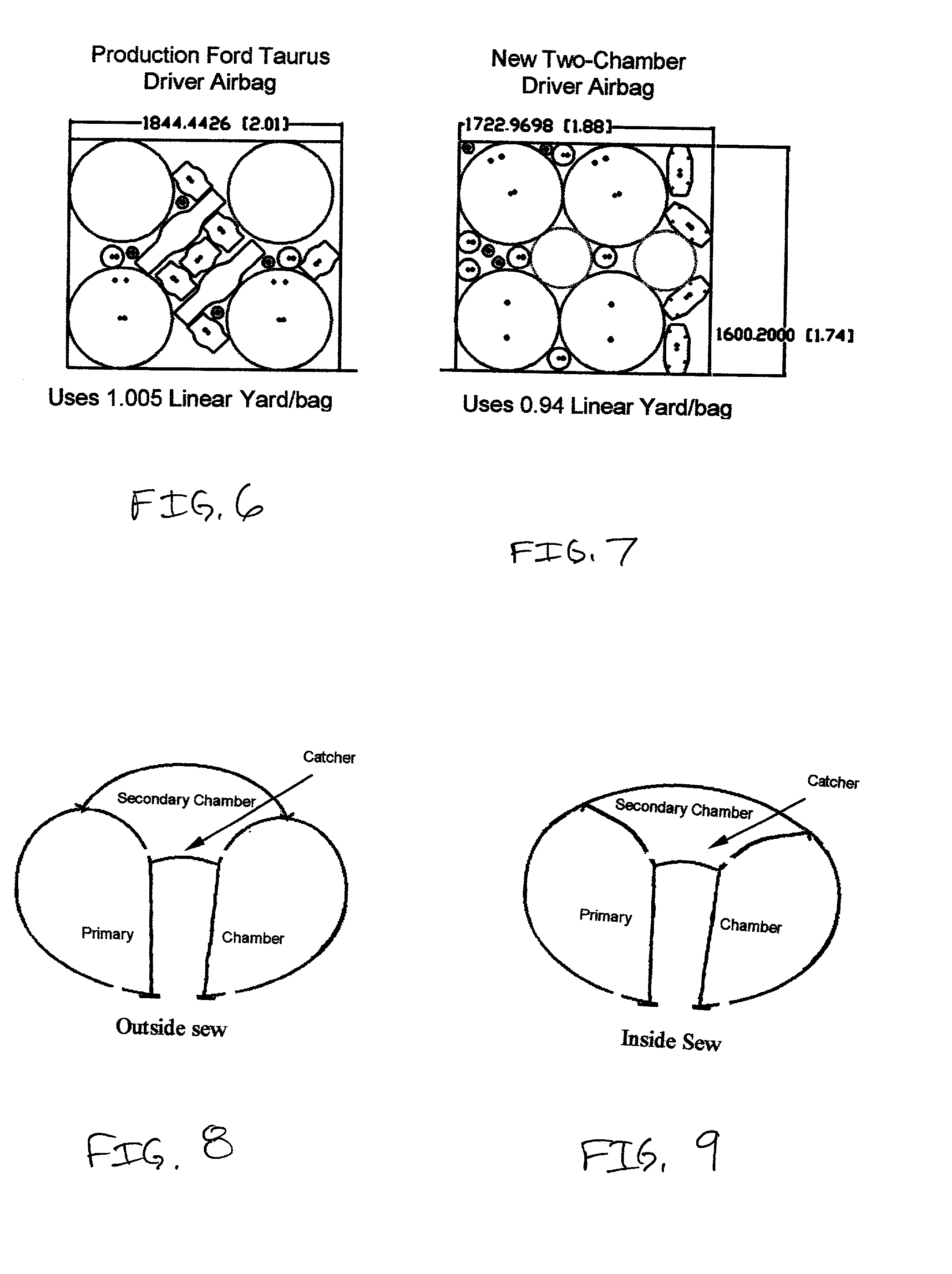
Furthermore, since the costs of producing airbag fabrics are relatively high and there is a general need to reduce such costs, there is a consequent need to more efficiently make use of the fabric by lowering the amount which needs to be cut (cutting operations also translate into higher labor costs), reducing the amount of fabric used in order to provide substantially lower packing volumes (in order to reduce the size of the airbag modules in cars since available space on dashboards, doors, and the like, are at a premium within automobiles), and reducing the shipping weight of such products (which translates into lower shipping costs), as well as other highly desired reasons.
However, it has been problematic to reduce such utilized fabric amounts in the past without consequently also reducing the available inflation airspace volume within the cushion product.
Such a desired method and product has not been available, particularly for passenger-side airbags which, as noted previously require greater amount of fabric for larger volumes of air (gas) to provide the greatest amount of protection area to a passenger.
With greater amounts of fabric needed, generally this has translated into the need for longer seams to connect and attach fabric panels, which in turn translates into greater amounts of time needed for sewing, and the like, operations.
It is more difficult to construct hence higher cost.
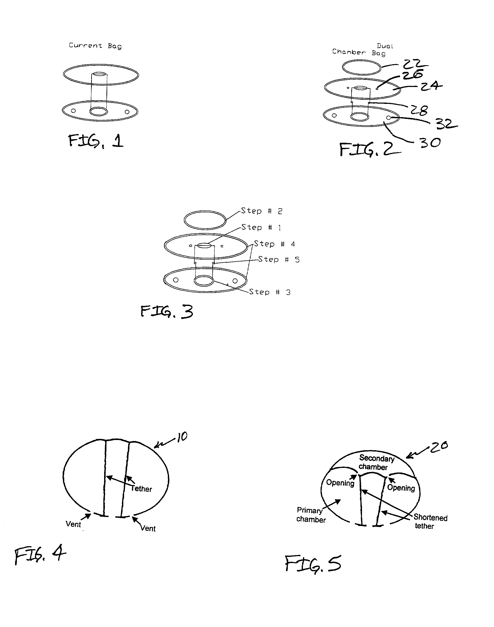
Also it is difficult to put tethers in such bags to control the final shape of the deployed bag.
The vent is from the outer bag, thus the outer bag may be too weak to protect a larger and heavier occupant.
In the case where the driver is sitting just farther than the flap release position, the effect may be fatal.
However, due to the complicated design, the fabrication cost will be high.
This could be very dangerous to a short occupant sitting close to the airbag considering the fact that the excursion of the primary chamber is rather high, especially when the occupant is tilted sideways at the instant of collision.
A driver-side airbag will generally comprise a low amount of utilized fabric but also does not provide a correlative high volume of available airspace; and the prior art passenger-side airbags require large amount of fabric.
Although the available inflation airspace volume in such conventional passenger-side airbags is rather large, the total amount of utilized fabric is too large to meet the aforementioned preferred effective fabric usage factor within that index.
Current single-chamber airbags have two significant drawbacks: First, they may exert a large rebound force on the occupant after deployment, putting the occupant at risk of possible neck injury.
Second, they may hurt rather than protect an occupant if the occupant is sitting very close to the airbag (as shorter and / or older drivers often do) when a collision occurs.
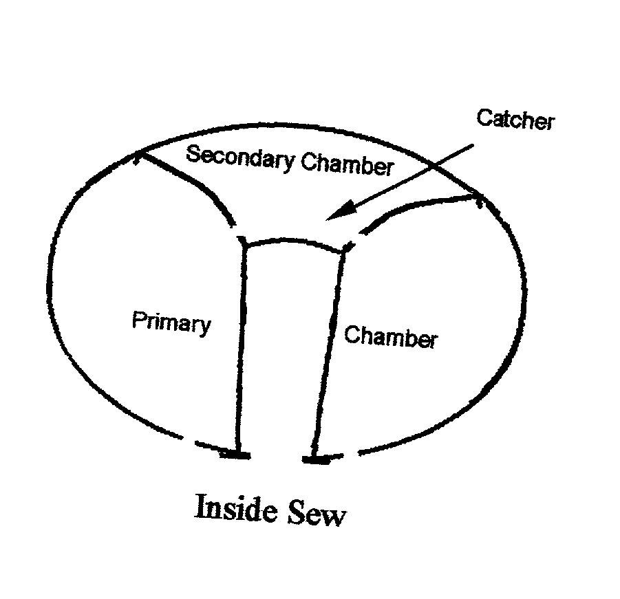
The current single-chamber airbag (FIGS. 1 and 4) has two significant drawbacks: First, it may exert a large rebound force on the occupant after it is deployed, putting the occupant at possible risk of neck injury.
Second, it may hurt rather than protect an occupant if the occupant is sitting very close to the airbag (as shorter and / or older drivers often do) when a collision occurs.

Method used


Image

  • Multiple chamber airbags and methods
  • Multiple chamber airbags and methods
  • Multiple chamber airbags and methods

Examples


Embodiment Construction

[0072] 1. Low cost and easy to construct: The two-chamber airbag is very manufacturing friendly. Most plants can produce such bags without any new equipment. The only extra cost is the piece of fabric that defines the outer surface of the secondary chamber.

[0073] 2. Tethered Design: The two-chamber airbag is tethered, it is very easy to control the shape and excursion of the deployed bag by controlling the length and position of the tether.

[0074] 3. Stronger secondary chamber: In the two chamber airbag design, the final vent of the secondary chamber is through the primary chamber, thus having a relatively strong secondary chamber.

[0075] 4. High safety performance: The two-chamber airbag provides a softer landing for the occupant. It significantly reduces the rebound, minimizing the injuries caused by the deploying airbag. It also provides protection for the short occupant sitting close to the airbag.

[0076] The secondary chamber may have other shapes, e.g. 3D. The secondary chamber m...


PUM


Abstract

A two or more chambered airbag provides much improved safety and / or performance. A modified single chamber airbag can be used as the primary chamber of the two-chamber airbag. A piece of fabric of appropriate size is sewn to the inside or outside surface of the front panel of the primary chamber to create the secondary chamber. One or more apertures are opened between the primary and secondary chambers. In order for the secondary chamber to inflate properly, the tethers of the primary chamber are shortened to 50% to 80% of their original length. The size or location of the tether sewing to the inner surface of the front panel of the primary chamber is also adjusted to create a desired shape of the secondary chamber when deployed.

Description

[0001] This application claims priority to and benefit of U.S. Provisional Patent Application Serial No. 60 / 216,545, filed Jul. 7, 2000, and hereby incorporated by reference.[0002] The present invention relates to a multi-chamber airbag or airbag cushion and method. Such a cushion may simultaneously exhibit a very low amount of fabric utilized to produce the target airbag cushion in correlation to an overall high amount of available inflation airspace within the cushion itself. These two correlative elements are combined in what is defined as an effective fabric usage index (being the quotient of the amount of fabric utilized in the construction of the airbag cushion and the available inflation airspace volume). A cushion exhibiting low seam usage factor, low total fabric weight, low fabric usage factor and / or comprising two or more chambers is provided as well as an overall vehicle restraint system including the inventive airbag cushion.BACKGROUND OF INVENTION[0003] All U.S. patent...

Claims


Application Information

Patent Timeline
Patent Type & Authority Applications(United States)
IPC IPC(8): B60R21/16B60R21/233B60R21/235B60R21/239
CPCB60R21/233B60R21/2338B60R21/239B60R2021/23324B60R2021/23382B60R2021/23504B60R2021/23533B60R2021/23576
Inventor WANG, YUNZHANGKESHAVARAJ, RAMESH
Owner MILLIKEN & CO
Why Eureka
Try Eureka