

Low leakage sleep mode for dynamic circuits
a dynamic circuit and low leakage technology, applied in the field can solve the problems that the use of dynamic logic circuits has not been as widespread, and achieve the effect of reducing power consumption and reducing leakag
- Summary
- Abstract
- Description
- Claims
- Application Information
AI Technical Summary
Problems solved by technology
Method used
Image

Examples
Embodiment Construction
[0021] The claims at the end of this application set out novel features which applicants believe are characteristic of the invention. The invention, a preferred mode of use, further objectives and advantages, will best be understood by reference to the following detailed description of an illustrative embodiment read in conjunction with the accompanying drawings.
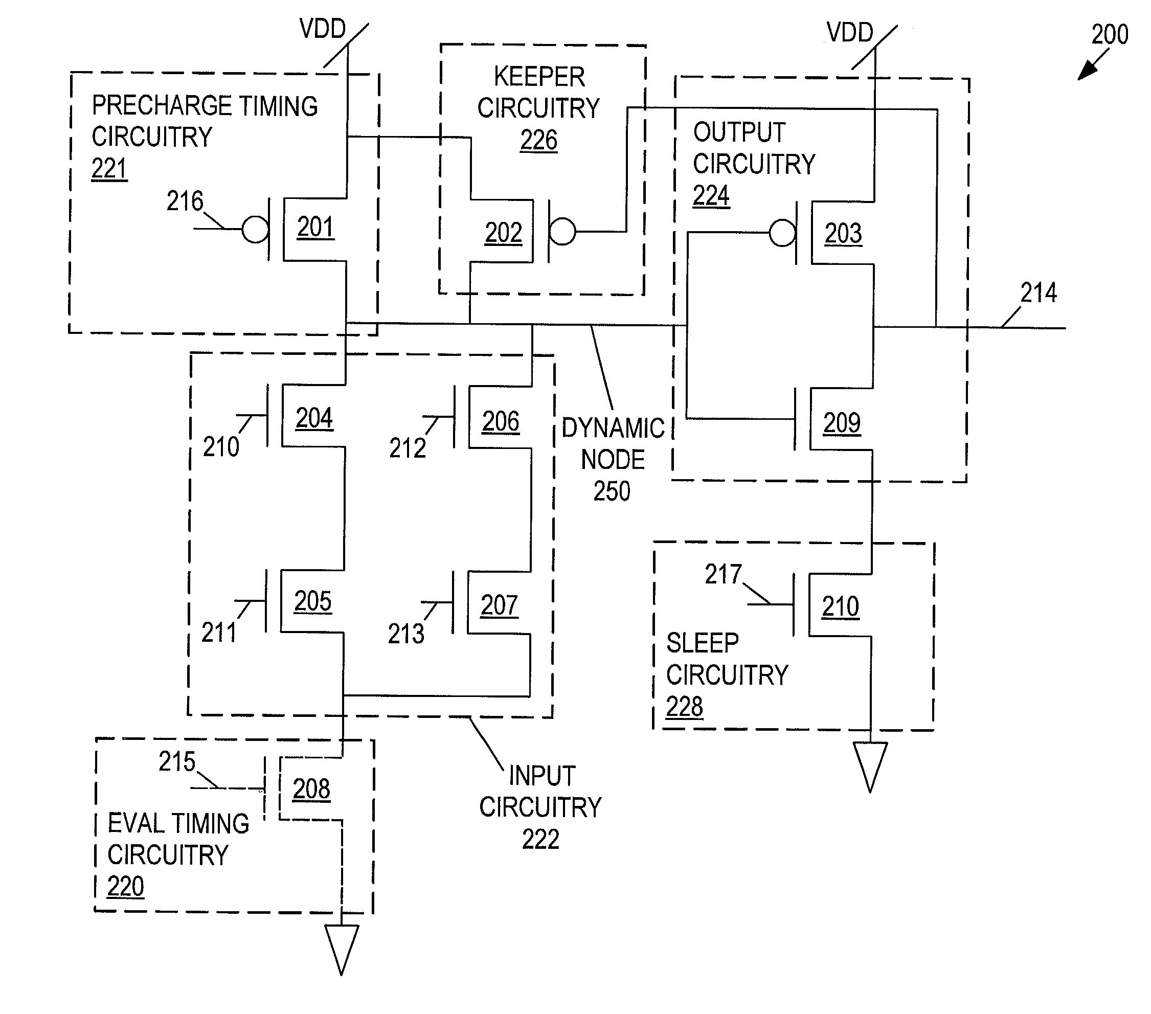
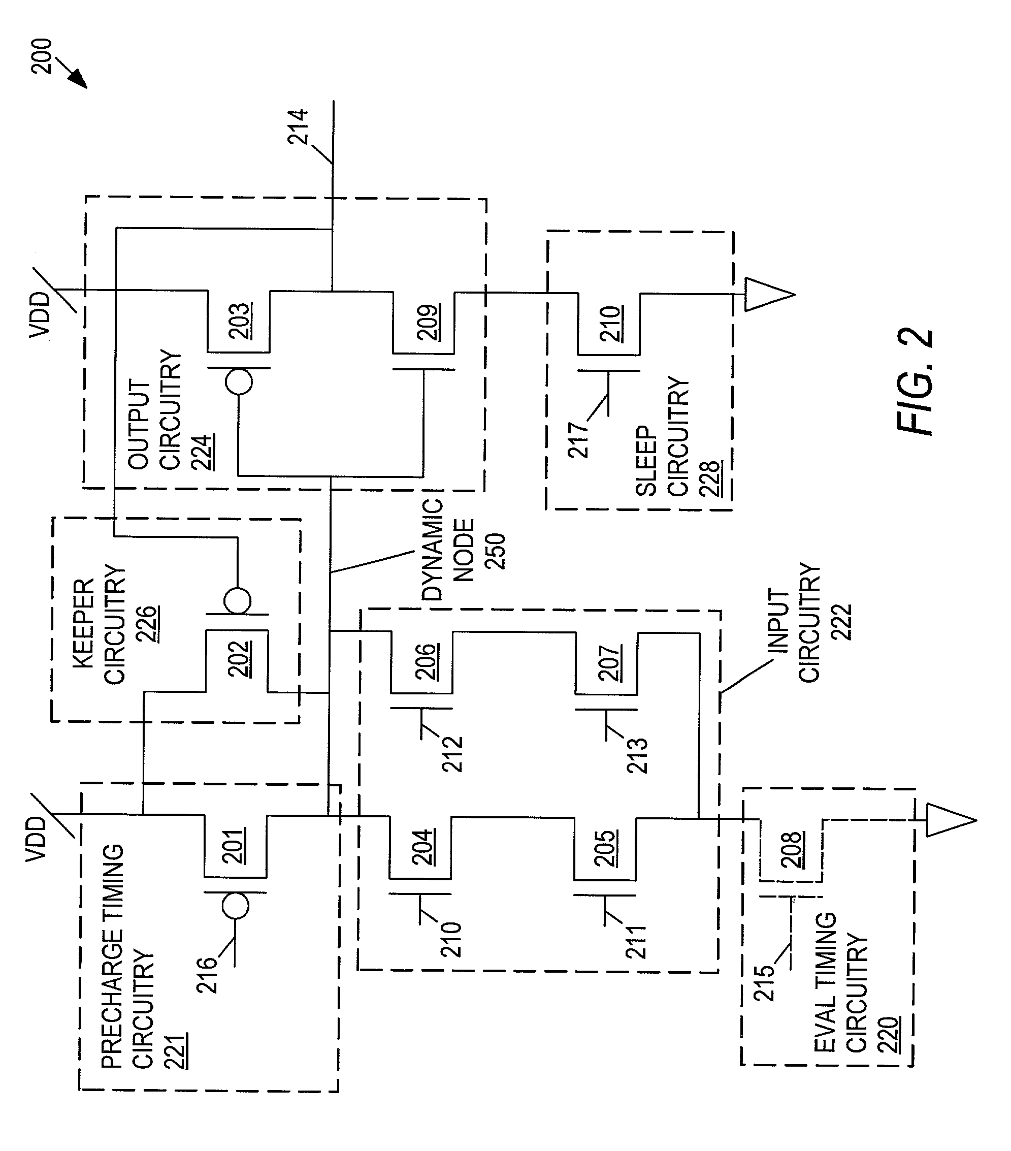
[0022] Referring now to FIG. 2, a dynamic logic circuit 200 is illustrated, according to an embodiment of the present invention. The circuit 200 has a dynamic node 250 which is directly coupled to precharge circuitry 221, keeper circuitry 226, output circuitry 224, and input circuitry 222. The precharge circuitry 221, keeper circuitry 226, and output circuitry 224 are each also coupled directly to Vdd, and keeper circuitry 226 is also coupled directly to the output 214 of output circuitry 224. The output circuitry 224 is also directly coupled to sleep circuitry 228, which in turn is coupled to ground. The input circuitry 222...
PUM
 Abstract
Description
Claims
Application Information