Image processing technique for images projected by projector

a technology of image processing and projector, applied in the field of image processing technique applied to images projected by projectors, can solve the problems of insufficient improvement of optical systems, inability to adequately solve the problem of out of focus projected image at such sites, and affecting the image quality of the image,

Active Publication Date: 2003-02-20
IBIDEN CO LTD +1
View PDF10 Cites 15 Cited by
  • Summary
  • Abstract
  • Description
  • Claims
  • Application Information

AI Technical Summary

Benefits of technology

0030] This arrangement enables the compensation coefficient to be read from the compensation coefficient storage module according to the requirements, thus ensuring high-speed image processing.

Problems solved by technology

The projected image at such sites is out of focus and rather blurred.
Any improvement of the optical system can not sufficiently solve this problem.
Namely the slight out-of-focus state at other positions lowers the image quality.

Method used


Image

  • Image processing technique for images projected by projector
  • Image processing technique for images projected by projector
  • Image processing technique for images projected by projector

Examples


Embodiment Construction

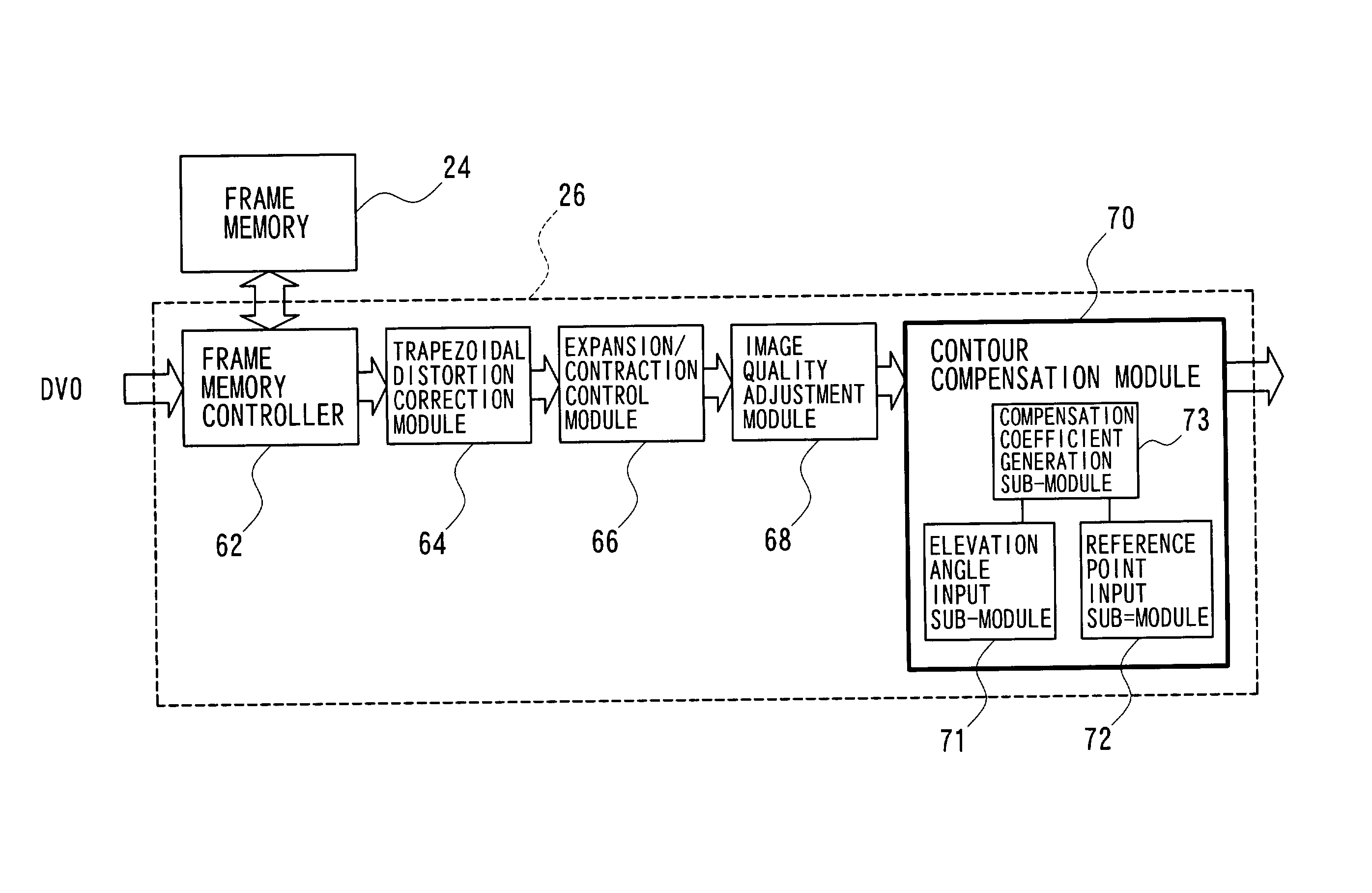
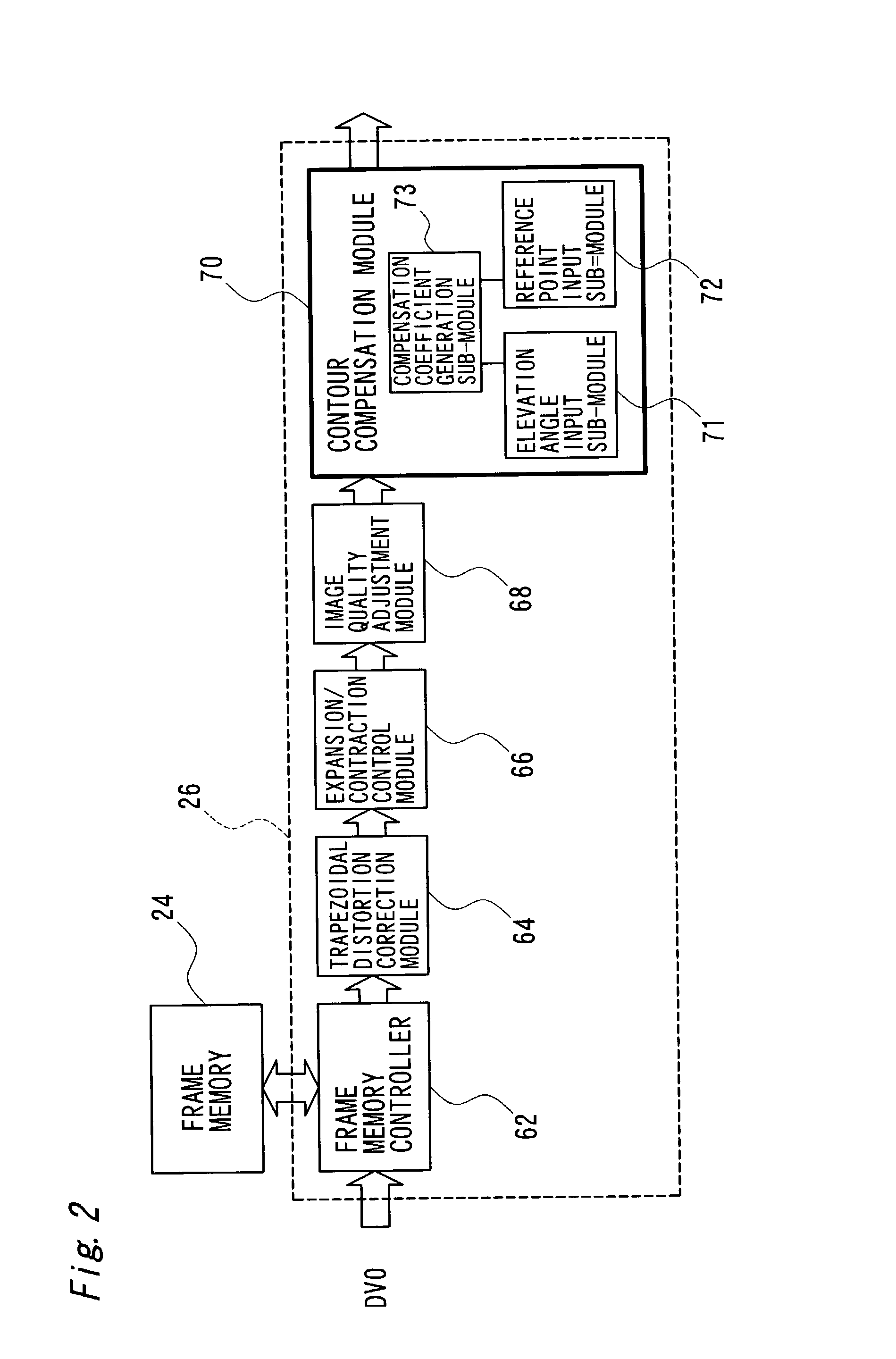
[0084] FIG. 10 is a block diagram illustrating the structure of a contour compensation module 70A in another projector 10A as a modified example. The projector 10A has an elevation angle detection module 78 and a reference point detection module 79, in addition to the constituents of the projector 10 of the above embodiment. The contour compensation module 70A is connected to these modules 78 and 79. The elevation angle detection module 78 measures distances to preset three points on the screen SC with an ultrasonic sensor, and automatically detects the vertical component and the horizontal component of the elevation angle based on the measurement result. Another means may alternatively be used to detect the vertical component and the horizontal component of the elevation angle. The detection result of the elevation angle detection module 78 is input into the elevation angle input sub-module 71 (see FIG. 2). The reference point detection module 79 includes an imaging device and a de...


PUM

PropertyMeasurementUnit
distanceaaaaaaaaaa
angleaaaaaaaaaa
elevation angleaaaaaaaaaa

Abstract

The technique of the present invention carries out specific image processing that emphasizes articulation of display with a varying degree of emphasis for respective sites of an image projected by a projector. A typical example of such image processing is sharpness adjustment. The degree of emphasis in sharpness adjustment at each site is specified, based on an elevation angle of the projector and a focalized position of the projected image. The technique of the invention thus readily prevents deterioration of the image quality due to out-of-focus state of the projected image.

Description

[0001] 1. Field of the Invention[0002] The present invention relates to an image processing technique applied for images projected by a projector.[0003] 2. Description of the Related Art[0004] A projector modulates light emitted from a light source based on image data with its light modulation means, such as a liquid crystal panel, and displays a resulting image on a screen. `Elevated projection` is often adopted to prevent any obstacle between the projector and the screen from interfering with the view of the projected image.[0005] FIG. 11 shows projection of an image on a screen SC with a prior art projector 100. In the example of FIG. 11A, an elevation angle, that is, an angle defined by an optical axis of the projector 100 and a normal line of the screen SC, is equal to 0. A resulting projected image P is rectangle without any significant distortion. In the example of FIG. 11B, the elevation angle is .theta. (.noteq.0). A resulting projected image P' has trapezoidal distortion o...

Claims


Application Information

Patent Timeline
Patent Type & Authority Applications(United States)
IPC IPC(8): G03B21/00G03B21/14G02F1/13G06T5/00H04N5/208H04N5/74H04N17/00
CPCG06T5/006H04N5/208H04N5/74H04N9/3185H04N9/3194
Inventor TAKEUCHI, KESATOSHINAKAMURA, KAZUYOSHI
Owner IBIDEN CO LTD
Why Eureka
Try Eureka