Log home fabrication process and associate log cutting machine

a technology of a log cutting machine and a log home, which is applied in the manufacture of wooden sticks, flat surfacing machines, manufacturing tools, etc., can solve the problems of laborious and labor-intensive process of making joinery cuts by hand on an irregularly shaped log, and the inability to greatly simplify the manufacturing process of logs with straight edges, etc., to achieve the effect of eliminating difficulties and disadvantages

Inactive Publication Date: 2003-03-06
HEARTHSTONE
View PDF0 Cites 16 Cited by
  • Summary
  • Abstract
  • Description
  • Claims
  • Application Information

AI Technical Summary

Problems solved by technology

But, in all cases, the straight edges of the log cant greatly simplify the manufacturing process.
Logs which still have the natural external contour of the raw timber log in place on opposed edges of the log cannot be so easily processed because the width of the log will vary along its length.
As compared to the joinery machine or other method of processing a rectangular timber cant, the process of making joinery cuts by hand on an irregularly shaped timber log is labor intensive, expensive, and much more prone to error.

Method used


Image

  • Log home fabrication process and associate log cutting machine
  • Log home fabrication process and associate log cutting machine
  • Log home fabrication process and associate log cutting machine

Examples


Embodiment Construction

)

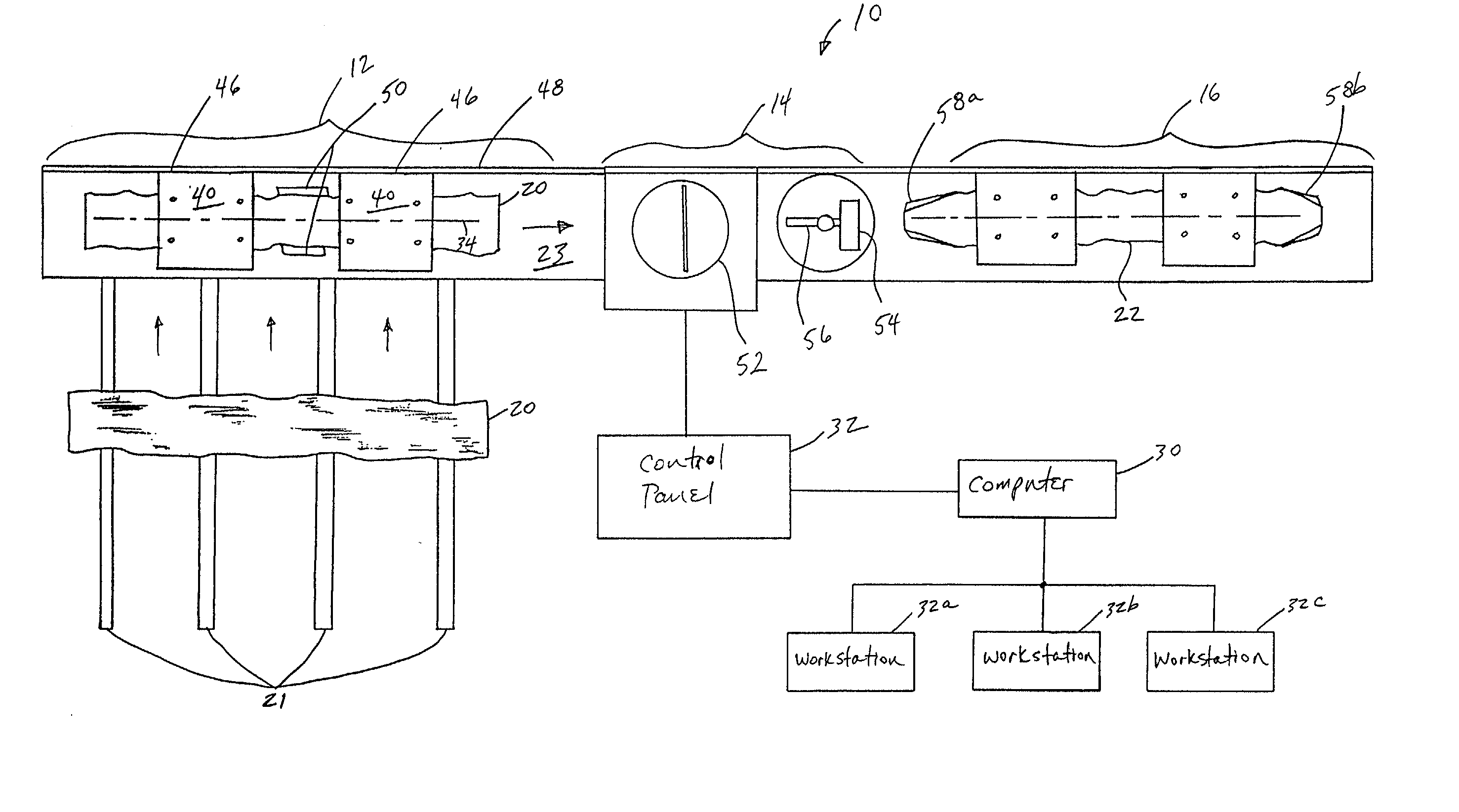
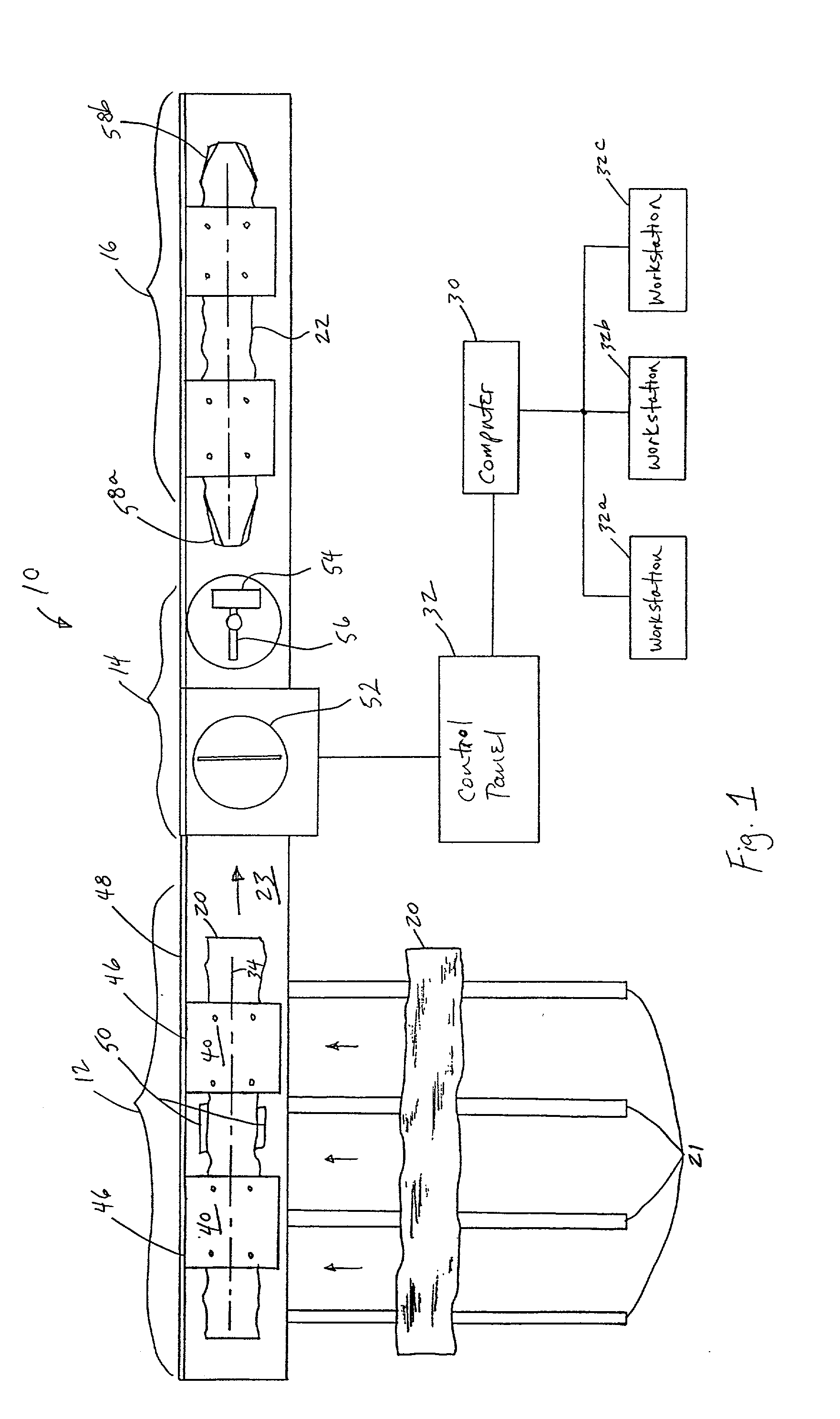
[0023] With reference now to the drawings in which like reference characters designate like or similar parts throughout the several views, FIG. 1 provides an overhead view of a log processing machine 10 according to the invention. The machine 10 is a specially designed joinery machine which processes logs 20 that will be incorporated into a log structure. A similar joinery machine capable of processing rectangular logs is available from Hundegger USA of Charleston, Utah under the product name K2. The machine 10 is capable of making a variety of high precision joinery cuts to the logs 20, including lap joints, dovetails, bird's mouth, and others.

[0024] Generally, the machine 10 includes an input section 12 where logs 20 are received, a processing section 14 where logs 20 are processed with the use of one or more cutting devices, and an output section 16 where processed logs 22 are removed from the machine 10. In a preferred embodiment, the machine 10 includes a computer 30 programme...


PUM

PropertyMeasurementUnit
lengthaaaaaaaaaa
heightaaaaaaaaaa
widthaaaaaaaaaa

Abstract

A log processing machine and associate method employs one or more log guides to make joinery cuts in a processed log which has at opposed edges of the processed log the raw log's natural external contour. In a preferred embodiment of the invention, each log guide includes a straight edge and is attached to the processed log to create an artificial straight edge for guiding the processed log through the joinery machine. Prior to attachment, centerlines are marked on the log guide and the processed log, and the centerlines are aligned when the log guide is attached to the processed log. The processed log, with the log guide attached, is then moved through the machine with the aid of computer control while the straight edge of the log guide follows a fence. In this manner, the position of the processed log and its centerline are always known so that the computer can make the programmed joinery cuts with high precision. An alternate embodiment of the invention employs one or more fence extensions as log guides. The fence extensions are positionable in guide channels formed in the contoured edges of the processed log. A further embodiment of the invention employs an opposed pair of clamping / alignment elements which are controlled by a computer to align and guide the log through the joinery machine.

Description

BACKGROUND[0001] 1. Field of the Invention[0002] The present invention relates generally to log structures and methods of constructing log structures. More particularly, the present invention relates to a log cutting machine and associate process of cutting logs for use in log structure construction.[0003] 2. Background of the Invention[0004] In the process of manufacturing log structures, raw logs from felled timber are typically hand selected and sent to the sawmill for processing. At the sawmill, two parallel cuts are made of the raw log to produce a log that is sawn flat on two parallel sides and then left with the natural contour of the original tree (less bark) on the two remaining surfaces. If desired, two further parallel cuts can be made of the log to remove the opposed natural contoured edges, producing a rectangular cant which will form a portion of the log structure. For log structures which specify a more natural looking log, the natural contoured edges are left on the ...

Claims


Application Information

Patent Timeline
Patent Type & Authority Applications(United States)
IPC IPC(8): B27B27/00B27B29/04B27B31/00B27B31/06B27C5/06B27C9/04B27F1/08
CPCB27B27/00B27B29/04B27B31/00Y10T29/5107B27C5/06B27C9/04B27F1/08B27B31/06Y10T83/6608Y10T83/736Y10T83/6568
Inventor GILES, RANDY K.
Owner HEARTHSTONE
Why Eureka
Try Eureka