
Apparatus and method especially for holding a separate piece to be attached to a unit load

a technology of a separate piece and a unit load, which is applied in the field of apparatus and methods for holding a separate piece to be attached to a unit load, can solve the problems of mechanical attachment, difficult to ensure the safety of the protector, and the edge of the material can become dirty throughout the entire length of the web, so as to achieve easy and rapid construction, easy and rapid process, and easy to test

Inactive Publication Date: 2003-04-03
PESMEL
View PDF6 Cites 2 Cited by
  • Summary
  • Abstract
  • Description
  • Claims
  • Application Information

AI Technical Summary

Benefits of technology

[0011] The apparatus according to the invention can be easily and rapidly constructed to handle varying situations, because in a factory environment pressurized air is readily available. The act of installing and directing the nozzles used for the production of air jets is a simple and rapid process that can be easily tested by means of practical experiments.
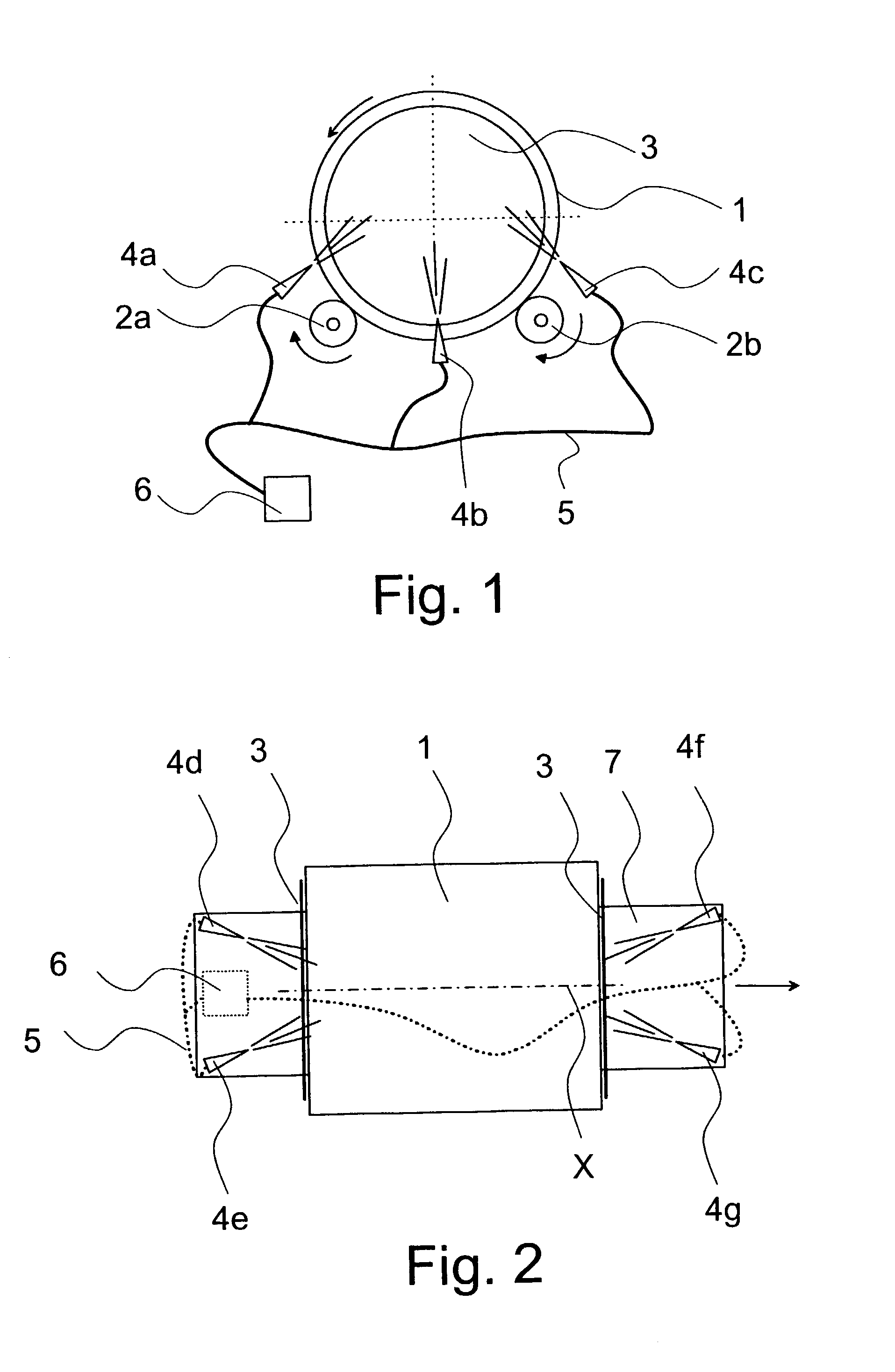
[0012] By means of a special embodiment of the invention it is possible to hold the end labels of moving rolls even though the air nozzles are installed in a stationary position.

Problems solved by technology

The attachment of the protectors is, however, problematic, because the adhesion of the same must be secured by means of adhesives or different kinds of adhesive tapes.
Especially adhesives dirty the end of the roll, and at the same time the edge of the material can become dirty throughout the entire length of the web.
Mechanical attachment, on the other hand, breaks and tears the material in the roll.
In this case the disadvantage that occurs is that the wrapping process is interrupted, which decelerates and disturbs especially continuous automatic production.
The protector can, of course, be attached to the piece only after the wrapping, but in such a situation it will not protect the piece from the mechanical effects caused by the wrapping film and the wrapping process.
Large amounts of adhesives are also a problem in view of work safety.
If the protector is detached, the information contained therein is also lost.

Method used


Image

  • Apparatus and method especially for holding a separate piece to be attached to a unit load
  • Apparatus and method especially for holding a separate piece to be attached to a unit load
  • Apparatus and method especially for holding a separate piece to be attached to a unit load

Examples


Embodiment Construction

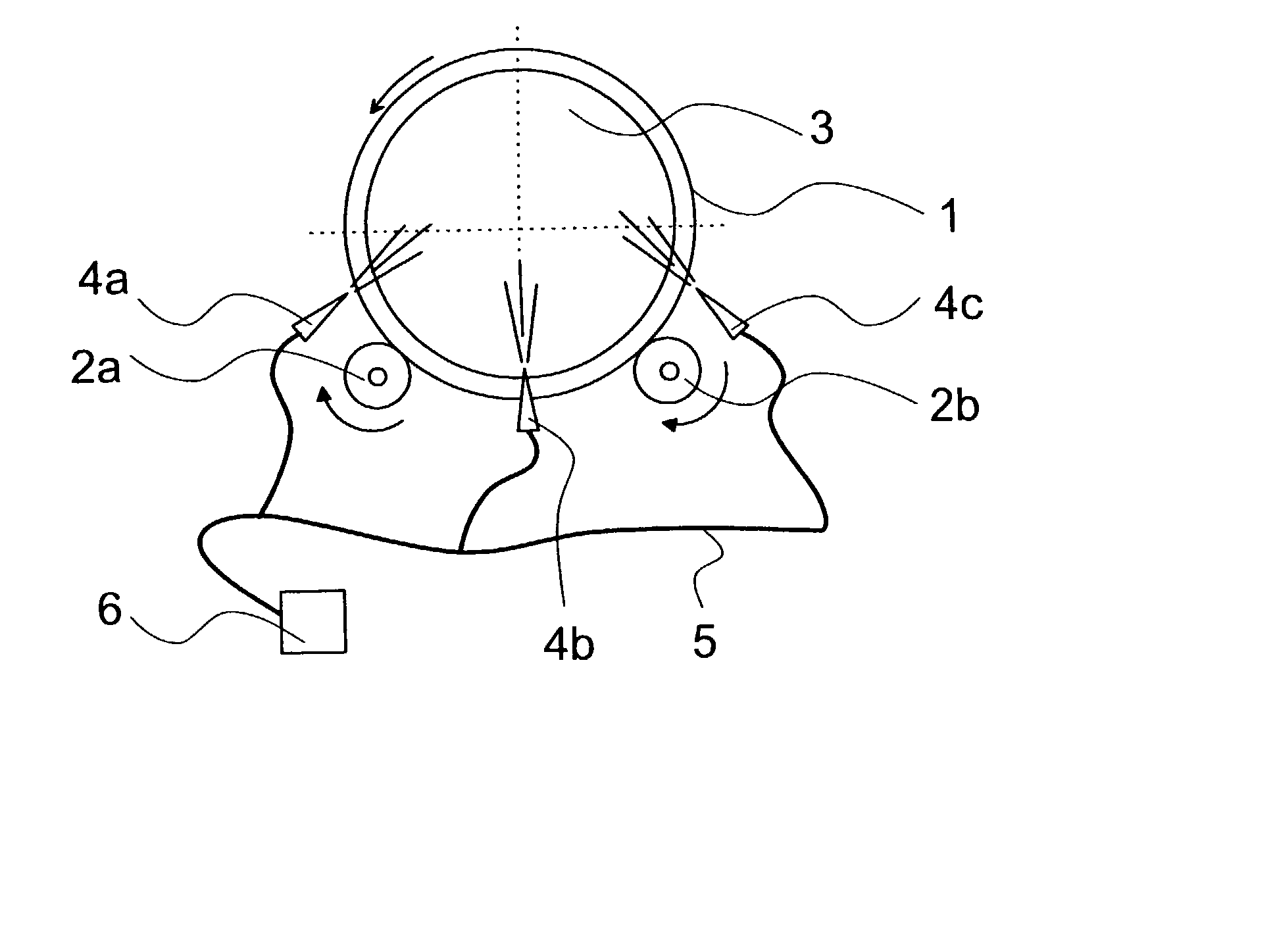
[0019] FIG. 1 shows a reduced principle view of the invention, in which only the essential aspects of the different structures have been shown. The technique used for the transfer and rotation of the roll is known as such, and thus the operation of the same will not be discussed in more detail in this context. A paper roll 1 is used as an example. The roll 1 is rotated around its longitudinal axis by means of two rotating rollers 2a, 2b. The rollers 2a, 2b are rotated by motor means around axes of rotation that are parallel to the longitudinal axis of the roll 1. The rotating apparatus is known as such and comprises for example the necessary frame structure. A continuous belt can also be passed via the rollers 2a, 2b that are typically longer than the roll 1, wherein the roll 1 rests on the support of the belt, and smaller surface pressures are attained.

[0020] Against the end of the roll 1 an end protector 3 has been placed for example manually or automatically by means of an appara...


PUM


Abstract

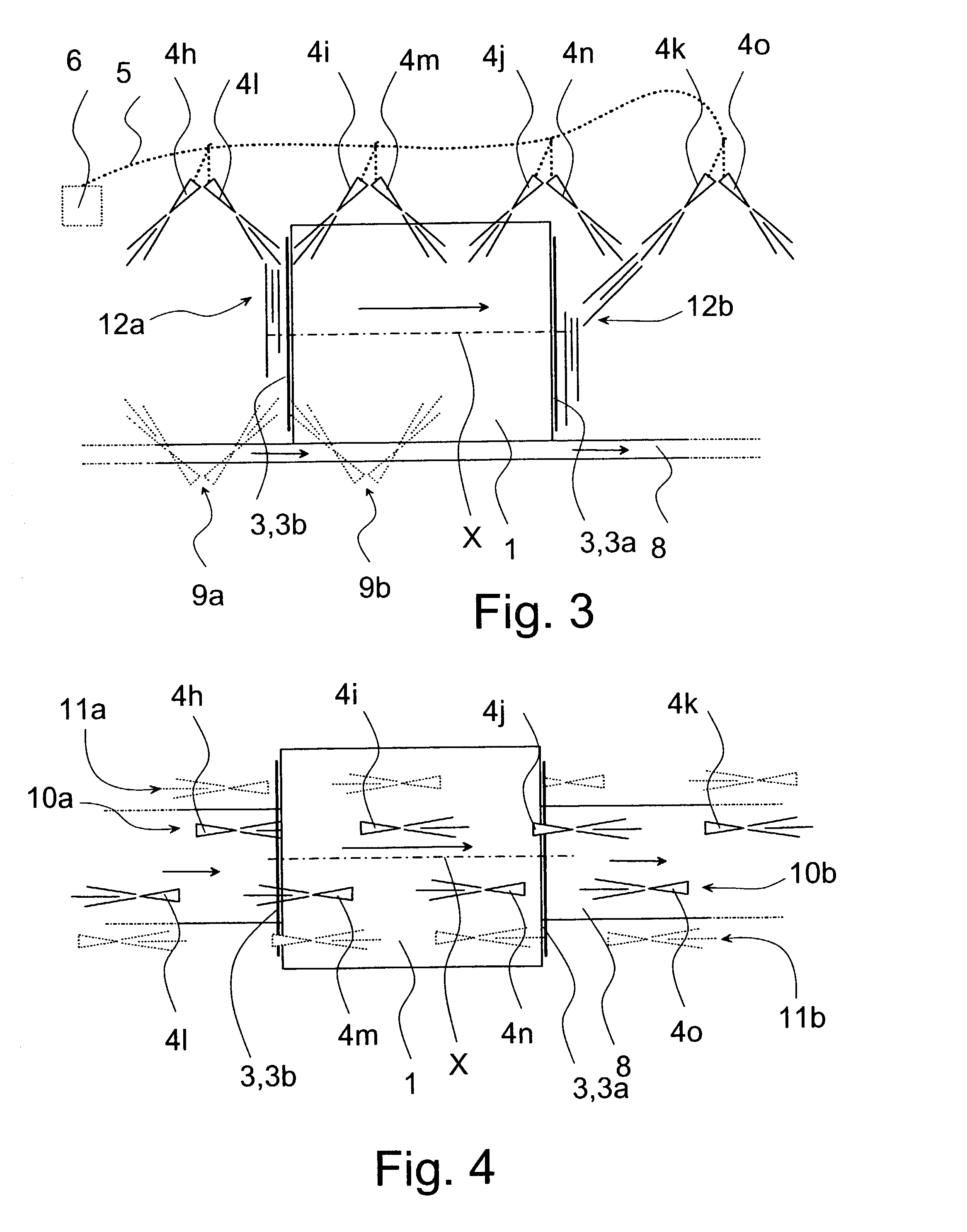
Method for holding in its place a separate piece placed against a side surface of a basic piece, wherein an air jet is directed to the separate piece and under this influence the separate piece is pressed against the end. Means for producing the air jets are placed for example in a stationary position or the basic piece is conveyed by a transfer carriage to which the means for producing the air jets are placed and arranged to hold at least one separate piece in its place. Alternatively, the basic piece is transferred by means of a conveyor or a transfer carriage and the means for producing the air jets are placed along this route in a stationary position and are arranged to hold in its place at least one separate piece that moves along the basic piece.

Description

[0001] The present invention relates to a method for holding in its place a separate piece placed against the side surface of a basic piece.[0002] According to prior art for example substantially cylindrical pieces, especially rolls in which different paper grades have been wound as a continuous web, are wrapped into a transparent stretch film. The purpose of the wrapping is to protect the piece from external mechanical effects, from the dirt in the environment as well as from other impurities and moisture. The material wound on the roll is for example printing paper, copying paper or soft tissue.[0003] The stretch film is typically an elastic, transparent film made of plastic material that is wrapped around the outer shell of a piece and typically around the end surfaces of the same as well. For the purpose of wrapping the shell, there are radial wrapping apparatuses in use, in which a horizontal piece is rotated around a longitudinal axis, for example by means of rotating rolls or...

Claims


Application Information

Patent Timeline
Patent Type & Authority Applications(United States)
IPC IPC(8): B65B25/14
CPCB65B25/148
Inventor MAKI-RAHKOLA, JARI
Owner PESMEL
Learn More