Method of constructing liquefied gas storage tank on land

a technology of liquefied gas and storage tanks, which is applied in the direction of mechanical equipment, vessel construction details, building repairs, etc., can solve the problems of consuming considerable time for construction, and achieve the effect of quick and easy construction

Inactive Publication Date: 2014-01-14
KOREA GAS CORPORATION
View PDF17 Cites 0 Cited by
  • Summary
  • Abstract
  • Description
  • Claims
  • Application Information

AI Technical Summary

Benefits of technology

[0010]According to one embodiment, a method of constructing a liquefied gas storage tank on land enables rapid and easy construction of a cylindrical wall of the storage tank by stacking a plurality of pre-produced unit-wall structures to be stacked or superposed with respect to one another.

Problems solved by technology

Accordingly, the conventional liquefied gas storage tank has a problem in that considerable time is consumed for construction thereof.

Method used


Image

  • Method of constructing liquefied gas storage tank on land
  • Method of constructing liquefied gas storage tank on land
  • Method of constructing liquefied gas storage tank on land

Examples


Embodiment Construction

[0027]Embodiments of the present disclosure will now be described in detail with reference to the accompanying drawings in FIGS. 2-5.

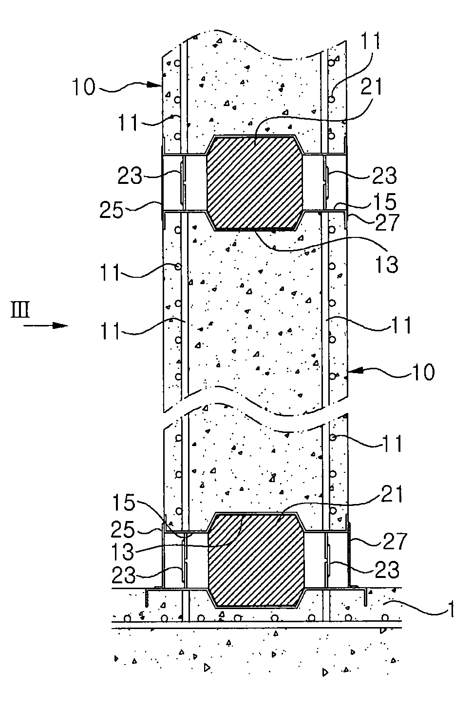
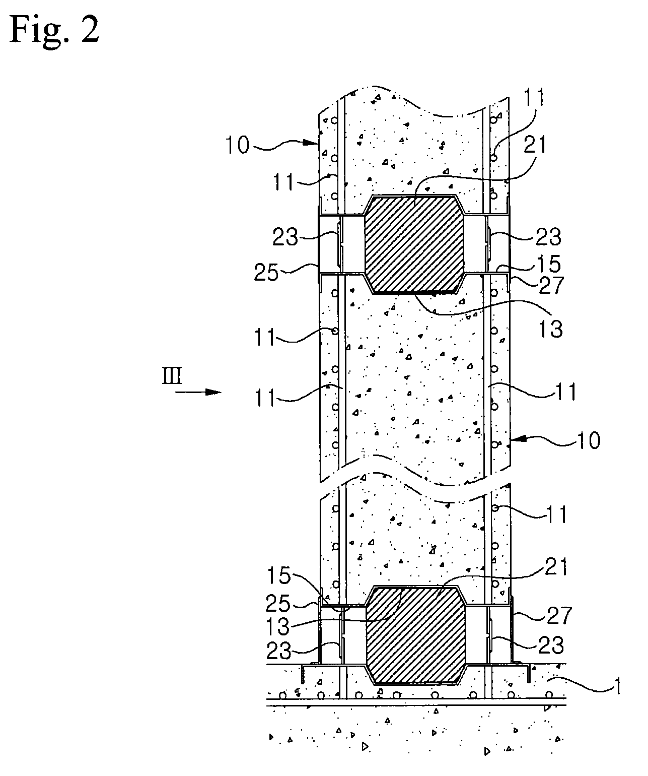
[0028]Referring to FIGS. 2 to 4, a liquefied gas storage tank on land in accordance with one embodiment is constructed by stacking a plurality of unit-wall structures 10 in an approximately cylindrical arrangement on a foundation or base 1. Each of the unit-wall structures 10 is made of concrete and has a parallelepiped shape wherein iron rods 11 are arranged lengthwise and breadthwise.

[0029]Since the storage tank has a cylindrical wall formed by stacking the unit-wall structures 10, each of the unit-wall structures 10 may be rounded to have a substantially arc shape as shown in FIG. 4. Here, since the storage tank has a much greater radius than the width of each of the unit-wall structures, the unit-wall structure will be described as having a substantially parallelepiped shape hereinafter.

[0030]Each of the unit-wall structures 10 has grooves 13 on up...


PUM


Abstract

The present disclosure relates to a method of constructing a liquefied gas storage tank on land, which enables rapid and easy construction of walls of a cylindrical storage tank by stacking a plurality of pre-produced unit-wall structures to be stacked or superposed with respect to one another. The method includes: producing unit-wall structures made of concrete and each having iron rods arranged lengthwise and breadthwise therein, stacking the unit-wall structures in a cylindrical arrangement, and connecting the unit-wall structures adjacent and in longitudinal and lateral directions with respect to each other to form a wall of the storage tank.

Description

CROSS REFERENCE TO RELATED APPLICATION[0001]This application claims priority from and the benefit of Korean Patent Application No. 10-2009-0106530, filed on Nov. 5, 2009, which is hereby incorporated by reference for all purposes as if fully set forth herein.BACKGROUND[0002]1. Technical Field[0003]The present disclosure relates to a method of constructing a liquefied gas storage tank on land and, more particularly, to a method of constructing a liquefied gas storage tank on land, which enables rapid and easy construction of a cylindrical wall of the storage tank by stacking a plurality of pre-produced unit-wall structures to be stacked or superposed with respect to one another.[0004]2. Description of the Related Art[0005]Generally, a liquefied gas storage tank on land has a substantially cylindrical flat bottom and is used to store liquefied gas for fuels, such as liquefied natural gas (LNG), liquefied petroleum gas, and the like, and other liquefied gases such as liquefied oxygen, ...

Claims


Application Information

Patent Timeline
Patent Type & Authority Patents(United States)
IPC IPC(8): E04B2/68E04H7/18E04B2/40E04B1/16E04B1/04
CPCF17C2203/012E04B2/68E04B2/40F17C2201/032F17C2201/0109F17C1/08F17C2201/052F17C2201/0119E04H7/18
Inventor YANG, YOUNG MYUNGYOON, IHN SOOSEO, HEUNG SEOKKIM, YOUNG KYUN
Owner KOREA GAS CORPORATION
Why Eureka
Try Eureka