Apparatus and a method for constructing an underground continuous filling wall and stratum

a technology of underground continuous filling and apparatus, which is applied in the direction of bulkheads/piles, soil preservation, artificial islands, etc., can solve the problems of difficult to form a deep wall, difficult to provide the underground continuous wall simultaneously, and the ground water tends to leak into, etc., to achieve simple processes, shorten the construction period, and widen the use field

Inactive Publication Date: 2011-11-22
SHREIDER VLADIMIR ANATOL +1
View PDF16 Cites 2 Cited by
  • Summary
  • Abstract
  • Description
  • Claims
  • Application Information

AI Technical Summary

Benefits of technology

[0008]It is, therefore, an object of the invention to provide more efficient apparatuses such as an apparatus for constructing an underground, substantially smoothly continuous, multifunction compacted filling structure such as a vertical preferably drain, diaphragm, anchor and foundation wall and a horizontal preferably drain and diaphragm stratum and the like that being formed in the ground in a broadened field of use and in simple processes in a shorter construction period.
[0009]It is another object of the invention to provide construction methods for constructing the underground filling walls and stratums, which methods are able easily and rapidly construct the underground continuous stratum and wall without joints and without any risk of leakage of ground water with the use of the apparatuses.

Problems solved by technology

Slurry or bentonite solution layers interrupt the formation of the continuous wall so that after completion of the wall, ground water tends to leak into the inside of the continuous walls through the joints.
It is therefore very difficult to provide the underground continuous wall simultaneously having two functions as foundation wall and a diaphragm wall.
Significant defects of the apparatus and method of its advancement are: it is very difficult to form a deep wall in the stony ground and a horizontal stratum; the cantilever endless chain cutter being advanced that requires a huge traction force and stabilizing moment applied to the trolley; the cutter is not capable to compact the filling wall being formed and for forming a compacted running filling there is needed much more hardening liquid.
Significant defects of that barrier wall installation system are the similar as shown above and following: the wall may be shaped into plane and vertical cylindrical surfaces only because of the cylindrical shape of a roll of the liner material; it is difficult to use a wide liner material of a width that is sufficient to reach a first confining bed.

Method used


Image

  • Apparatus and a method for constructing an underground continuous filling wall and stratum
  • Apparatus and a method for constructing an underground continuous filling wall and stratum
  • Apparatus and a method for constructing an underground continuous filling wall and stratum

Examples


Embodiment Construction

[0075]In the describing of the preferred embodiments of the invention illustrated in the drawings, specific terminology will be resorted to for the sake of clarity. However, the invention is not intended to be limited to the specific terms so selected, and it is to be understood that each specific term includes all technical equivalents which operate in a similar manner to accomplish a similar purpose.

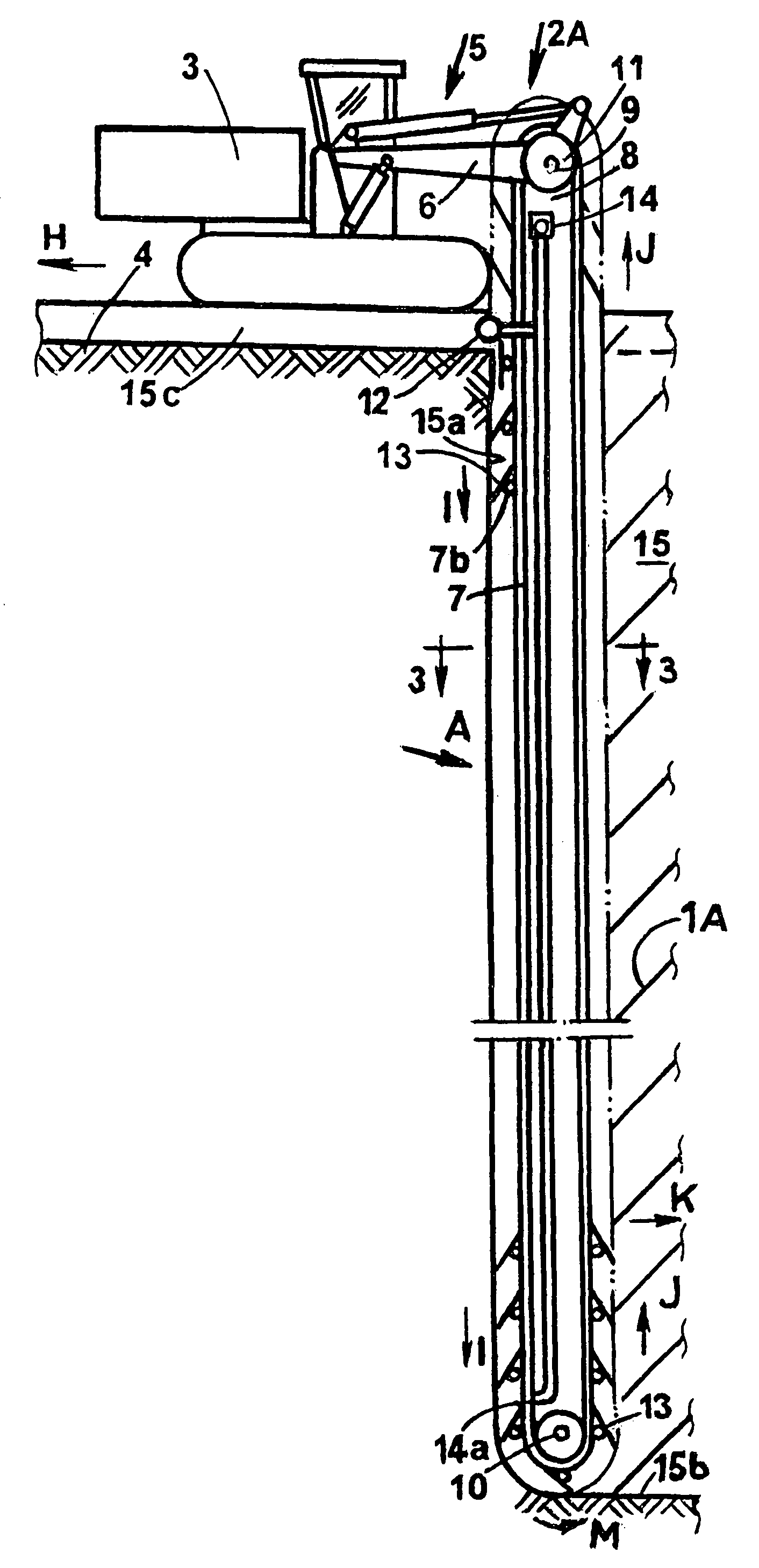
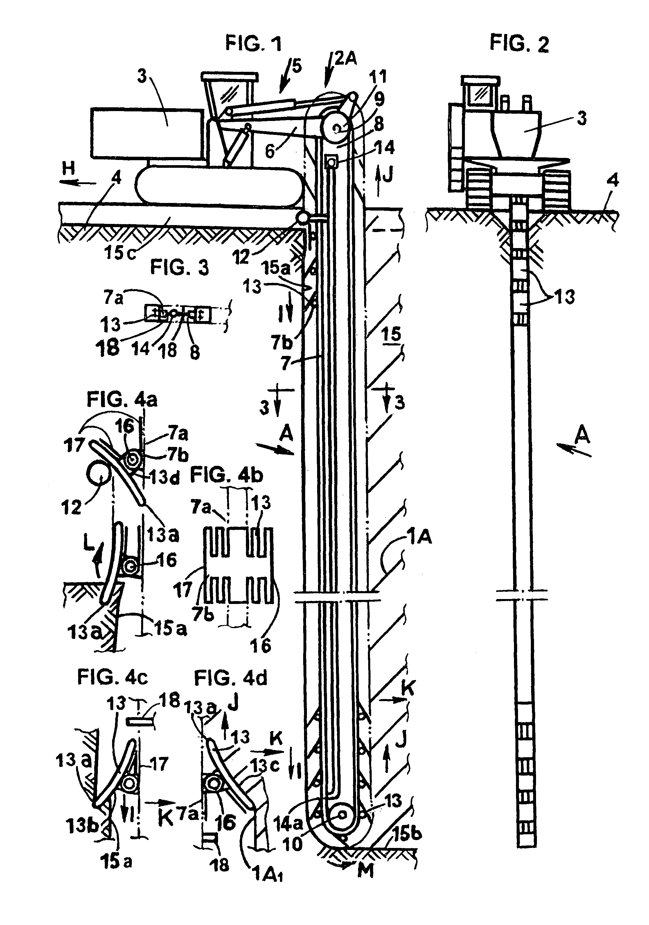
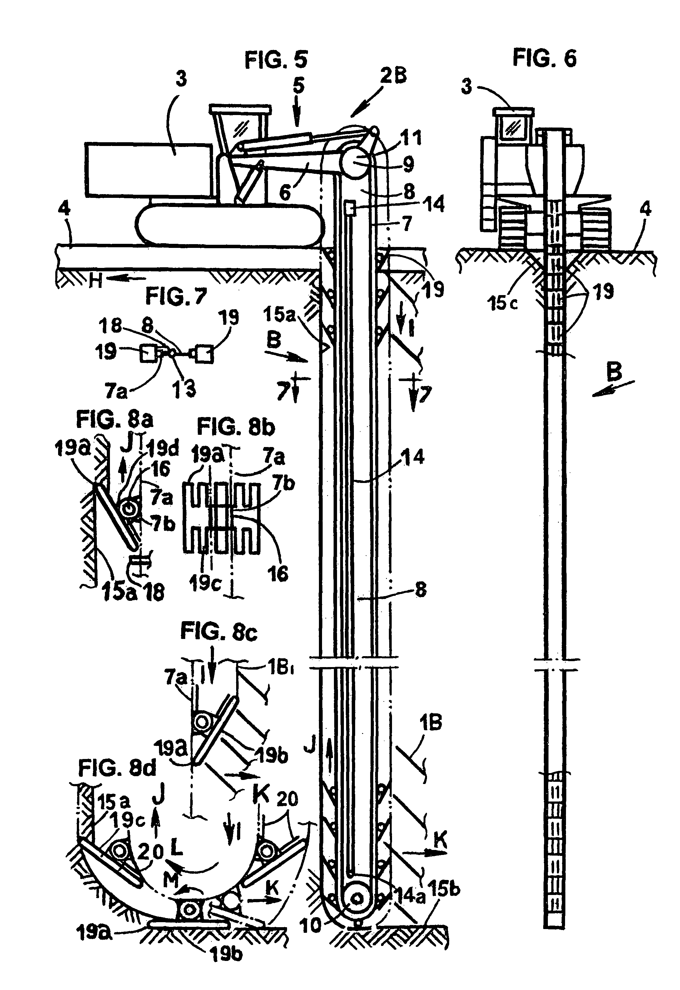
[0076]An underground continuous compacted filling structure such as a horizontally extending vertical preferably wall and a horizontal preferably stratum that is constructed with the aid of the apparatus depicted in the drawings embodying the teachings of the subject invention. Each of later described and illustrated embodiments of the constructing apparatus has a means for compressing a frontal working face of the filling structure to form the compacted filling structure. Each of later described and illustrated modifications of the compressing means is able to force a filling from its...


PUM


Abstract

A number of slot filling-compressing members are inserted from a framework into and across a slot-shaped excavation at ahead of a frontal face of a continuous, compacted slot filling being formed along the slot, and moved with a drive means connected to the members for intermittently forcing portions of the members against the filling to compress the filling adjacent to the members longitudinally against the face. The compacted filling is in this way formed by longitudinal pressure. The members can be mounted for forward or reciprocating movement in directions along and across the face.

Description

CROSS-REFERENCE TO RELATED APPLICATIONS[0001]This application is instead of an application Ser. No. 11 / 796,149, filed on Apr. 27, 2007 as 371(c) date because partly lost when being sent and now cancelled.STATEMENT REGARDING FEDERALLY SPONSORED RESEARCH OR DEVELOPMENT[0002]Not ApplicableREFERENCE TO SEQUENCE LISTING, A TABLE, OR A COMPUTER PROGRAM LISTING COMPACT DISC APPENDIX[0003]Not ApplicableBACKGROUND OF THE INVENTION[0004]The present invention relates to apparatuses for excavating ground and constructing underground continuous, draining and retaining vertical wall- and horizontal stratum-shaped structures of a hardening liquid-excavated ground mixture or ready-mixed concrete or sand, especially to control a ground gas and water flow and to provide a drainage, isolation, containment and separation of subsurface environments, prevention of a leakage through levees and isolation of contaminated and sensitive areas, as anchors and foundations, and to underground continuous wall-sha...

Claims


Application Information

Patent Timeline
Patent Type & Authority Patents(United States)
IPC IPC(8): E02F3/08
CPCE02D17/13E02F3/10E02F3/142E02F5/12
Inventor SHREIDER, VLADIMIR ANATOLSHREIDER, NATALIA
Owner SHREIDER VLADIMIR ANATOL
Why Eureka
Try Eureka