Drawbar and screen system

a technology of drawbars and screens, applied in the direction of moving filter elements, separation processes, filtration separation, etc., can solve the problems of screen damage, multiple tensioners on each screen side or end, and requires a relatively long time to change screens, so as to prevent less tension and sufficient strength

Inactive Publication Date: 2003-04-10
VARCO I P INC
View PDF1 Cites 21 Cited by
  • Summary
  • Abstract
  • Description
  • Claims
  • Application Information

AI Technical Summary

Benefits of technology

0010] The present invention, in certain embodiments, provides a screen tension clamping apparatus that has one elongated draw bar that co-acts with a screen end hookstrip and is tensioned with a single bolt structure. In certain aspects, the single drawbar is substantially equal in length to the length of the screen end (or side) with which it is in contact. In one particular aspect the drawbar has an edge that is crescent shaped or curved to accommodate the typical slackening or bowing of the outer sides at the end of a screen that is put under tension on a vibratory separator or shaker. This curved shape insures that the ends of the screen are tightened as is the rest of the screen. Alternatively, the single drawbar has sufficient strength, e.g. by making it sufficiently large and / or massive, that tightening the drawbar prevents less tension being applied to the screen end's outer parts which can result in undesired inward bowing of a screen.

Problems solved by technology

The use of multiple tensioners on each screen side or end requires a relatively long time to change screens since each individual screen tensioner must be released and then tightened.
When multiple screen tensioners are used at each end of a screen, efforts have been made--which often are unsuccessful--to insure that each screen tensioner applies the same amount of tension to a screen.
If part of a screen is not tensioned properly, it may not perform properly and may lead to screen damage.

Method used


Image

  • Drawbar and screen system
  • Drawbar and screen system
  • Drawbar and screen system

Examples


Embodiment Construction

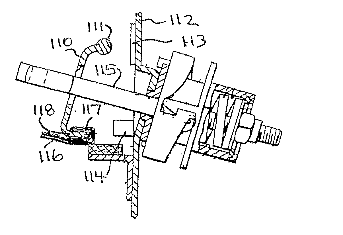
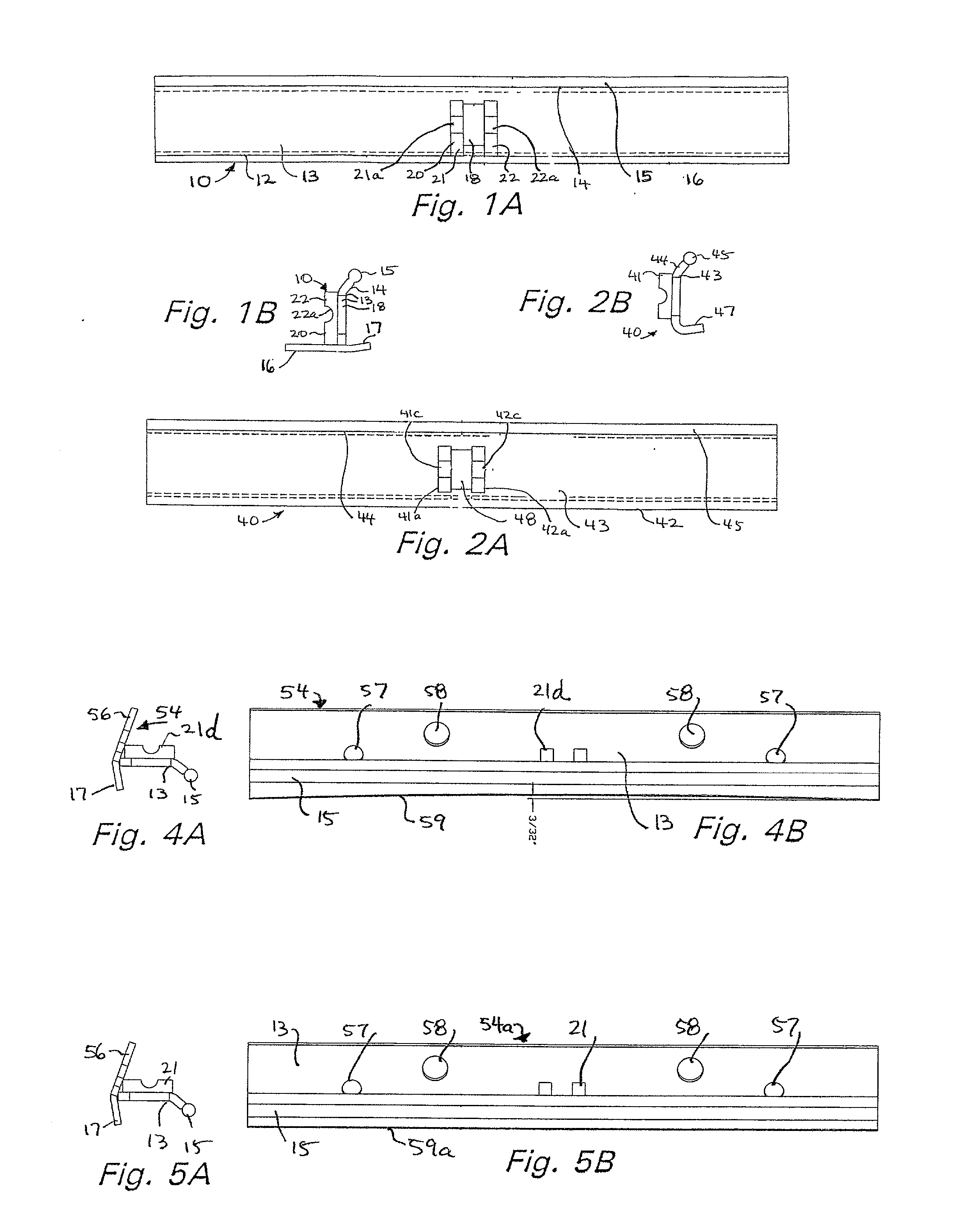
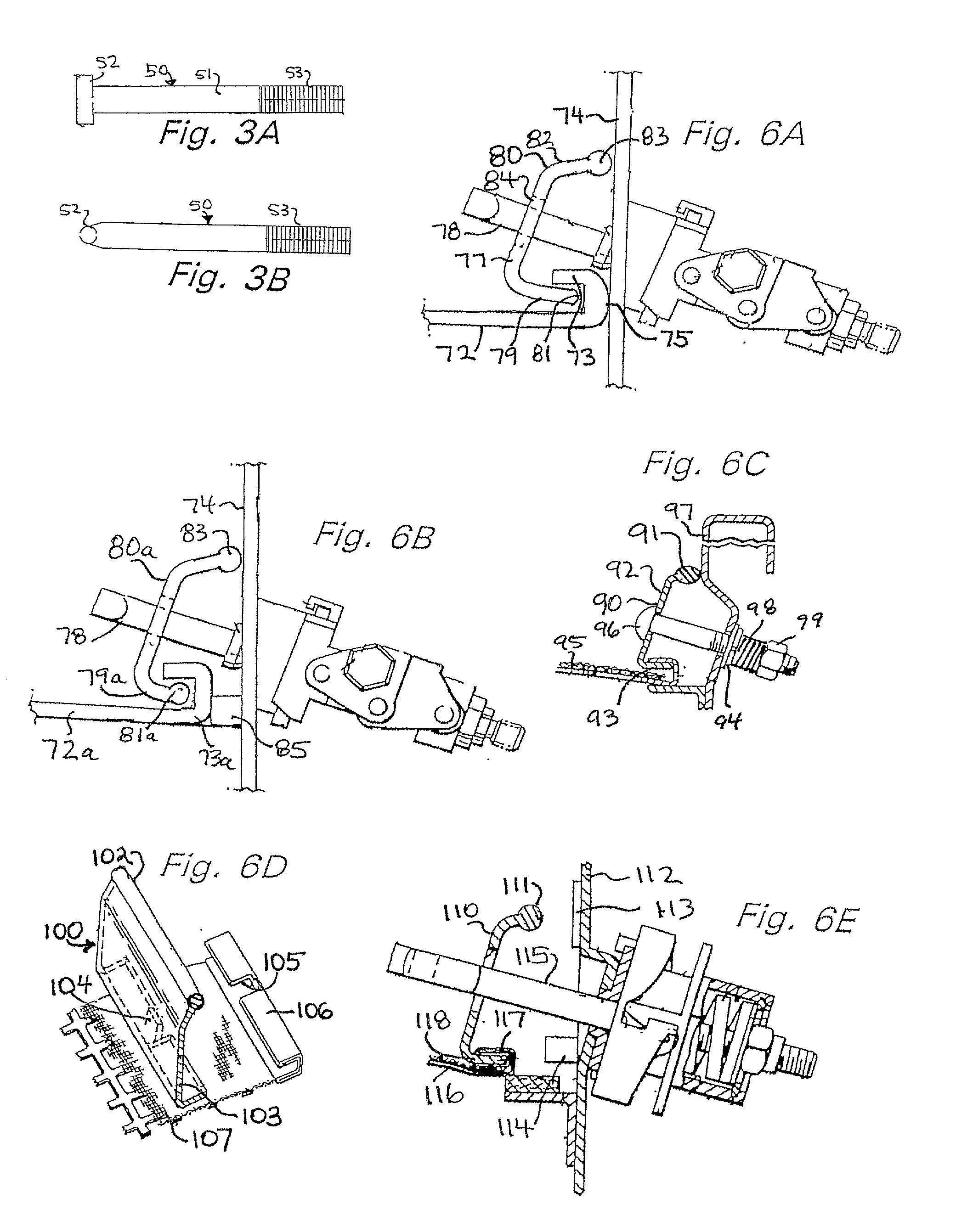
[0026] Referring now to FIGS. 1A-1C, a screen tension clamping apparatus 10 according to the present invention has a bar 12 with a main body 13, a top part 14, a top edge 15, an optional lower member 16 (which may be used for added weight and / or added stability) with a hook portion 17, a bolt holder 20, and a bolt hole 18 through which part of a tensioning bolt extends during use.

[0027] The bolt holder 20 (which is optional) has two spaced-apart side members 21, 22 each with a recess 21a, 22a, respectively in which part of a bolt end is received and held during use.

[0028] The top edge 15 of the top part 14 of the main body 13 is, preferably, rounded (although it is within the scope of this invention for it to be squared off). By thus rounding off the top edge, friction between the bar 12's top and the wall of a basket of a vibratory separator is reduced. This facilitates movement of the top of the bar with respect to the basket wall which helps the bar move into correct position. Us...


PUM

PropertyMeasurementUnit
dimensionaaaaaaaaaa
angleaaaaaaaaaa
lengthaaaaaaaaaa

Abstract

A clamp system for releasably securing a screen to a vibratory separator apparatus, and methods of its use, and a plate for such a system, the clamp system having, in certain aspects, a plate for contacting a screen end of a screen to be mounted to a vibratory separator apparatus, the plate having a plate linear dimension and the screen end having a screen linear dimension, the plate having a plate body, a bolt with a first end extendable through the plate and a second end extendable through part of the vibratory separator apparatus, the bolt tightenable in place to hold the plate in position with respect to the screen and the vibratory separator apparatus, and the plate linear dimension substantially equal to the screen end linear dimension.

Description

[0001] 1. Field of the Invention[0002] This invention is directed to clamping devices and drawbars for screens mounted on vibratory screening system; to such items for tensioning screens in vibratory separators; to systems with such devices; to screens for such systems and to methods of their use.[0003] 2. Description of Related Art[0004] There are a variety of known devices and apparatuses for securing a screen to a vibratory screening apparatus. Many of these systems employ a simple bolt, nut, and plate combination, with or without springs or shock absorbing material. Tightening and loosening of the nut provides tension adjustment. In many of the these systems, multiple screen tensioners on each end of a screen are used for each individual screen. In some cases multiple screen tensioners are required along a screen side because a tension rail may bow providing unequal tension along the screen side. The use of multiple tensioners on each screen side or end requires a relatively lon...

Claims


Application Information

Patent Timeline
Patent Type & Authority Applications(United States)
IPC IPC(8): B01D33/03B07B1/46B07B1/48
CPCB01D33/0376B07B1/46B07B1/4663B07B1/469B07B1/48B01D33/80
Inventor SEYFFERT, KENNETH W.MCCLUNG, GUY L. III
Owner VARCO I P INC
Why Eureka
Try Eureka