Light emitting device and communication system

a technology of light emitting devices and communication systems, applied in the direction of optical elements, close-range type systems, instruments, etc., can solve the problems of time-consuming and costly procedure for replacing many informations assigned to many identification-required objects, and the conventional technique of bar-code patterns, which is inconvenient to describe, and cannot achieve the effect of high data transmission speed of communication systems

Active Publication Date: 2003-04-10
SAMSUNG DISPLAY CO LTD
View PDF7 Cites 37 Cited by
  • Summary
  • Abstract
  • Description
  • Claims
  • Application Information

AI Technical Summary

Benefits of technology

[0021] It is a still further object of the present invention to provide a novel communication system capable of renewing and / or reproducing the informations attached to the identification-required object or re-writing the information stored in the storage unit attached to the identification-required object conveniently, however, without need for any additional procedures.
[0030] It is still more object of the present invention to provide a novel light-emitting device included in the communication system capable of renewing and / or reproducing the informations attached to the identification-required object or re-writing the information stored in the storage unit attached to the identification-required object without deterioration of appearance of the identification-required object.

Problems solved by technology

It is no doubt apparent that the fluorescent lamp is unsuitable for realizing a high data transmission speed of the communication system because the rising time of the luminance of the fluorescent lamp is extremely slow, for example, as slow as seconds-order.
The last-described conventional technique using the bar-code pattern is inconvenient because it is necessary for renewing the information to replace the bar-code pattern, which stores the old information into a new bar-code pattern which stores a new information.
The replacement of many informations assigned to many identification-required objects is time-consuming and costly procedure.
Two or plural bar-code patterns attached onto the identification-required object may cause deterioration in appearance of the identification-required object.
This removal process may also take a further longer time and a further cost.
In worst case, the removal process may provide any damage to the identification-required object.

Method used


Image

  • Light emitting device and communication system
  • Light emitting device and communication system
  • Light emitting device and communication system

Examples


Embodiment Construction

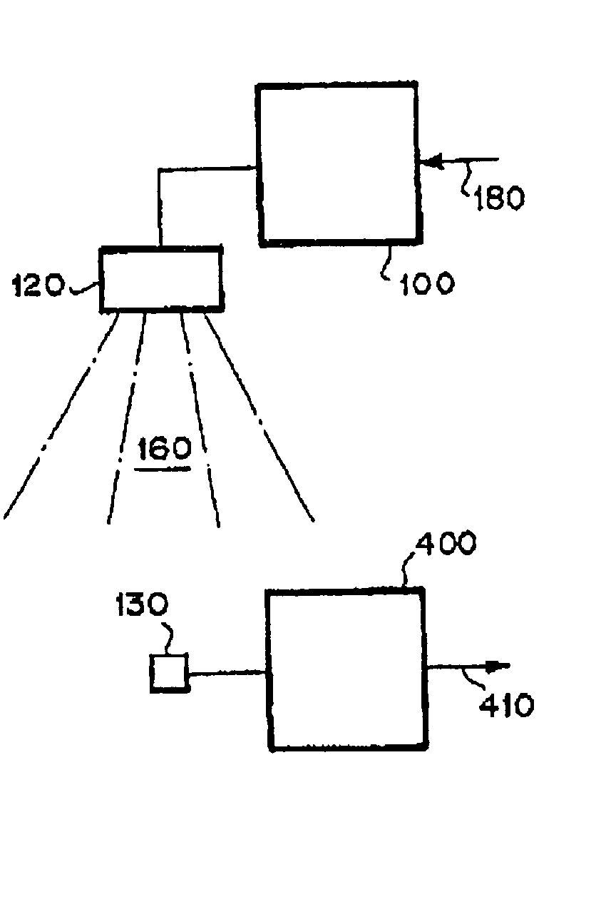
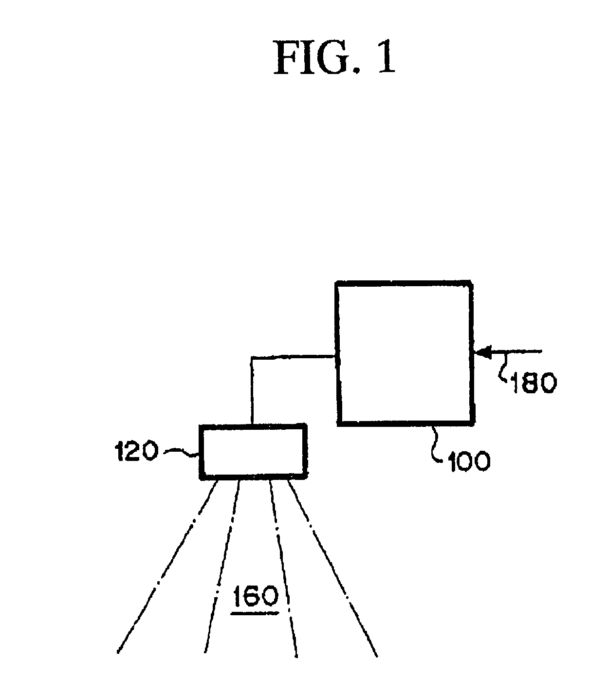
[0071] A preferred embodiment according to the present invention will be described in detail with reference to the drawings. The preferred embodiment provides a novel communication system including a new light-emitting device, wherein the communication system is suitable for realizing a high speed data transmission and is capable of renewing and reproducing informations attached to an identification-required object or replacing an information storage unit attached to the identification-required object conveniently, however, with no need for any additional procedures nor placing the third party in an allowable condition for knowing or being aware of the fact of the renewal and / or the old information as renewed, as well as without providing any substantive damage to the identification-required object and deterioration of appearance of the identification-required object.

[0072] The novel communication system including a new light-emitting device which realizes the above-desired communic...


PUM


Abstract

A communication system includes: at least one light-emitting device for emitting a light; and at least one light-receiving device for receiving the light emitted from the at least one light-emitting device. The light-emitting device further includes: at least one driver unit for generating a modified current based on an externally entered information signal; and at least one light-emitting unit operatively and functionally coupled to the at least one driver unit for receiving the modified current and emitting a modified signal light including any information based on the modified current. The at least one light-emitting unit includes at least one electroluminescence element.

Description

[0001] 1. Field of the Invention[0002] The present invention relates to a light emitting device for realizing an optical communication, and an optical communication device including a light emitting device as well as an optical communication system including a light emitting device[0003] All of patents, patent applications, patent publications, scientific articles and the like, which will hereinafter be cited or identified in the present application, will, hereby, be incorporated by references in their entirety in order to describe more fully the state of the art, to which the present invention pertains.[0004] 2. Description of the Related Art[0005] Some of the conventional techniques for realizing the information communication device and system by use of an illumination device have been proposed.[0006] Japanese laid-open patent publication No. 61-202536 discloses an optical communication method and system, wherein the system includes an illumination device and a light-receiving dev...

Claims


Application Information

Patent Timeline
Patent Type & Authority Applications(United States)
IPC IPC(8): H01L51/50H04B10/11H04B10/116H04B10/54H05B33/14
CPCH04B10/116H04B10/1149
Inventor ODA, ATSUSHIHAYASHI, KAZUHIKOTOGUCHI, SATORU
Owner SAMSUNG DISPLAY CO LTD
Why Eureka
Try Eureka