System and method for obtaining video of multiple moving fixation points within a dynamic scene

a dynamic scene and fixation point technology, applied in the field of image processing, can solve the problems of system still being unable to fixate on one point at a time, action must occur, and difficulty in adequately compensating for servo errors

Inactive Publication Date: 2003-04-24
CARNEGIE MELLON UNIV
View PDF26 Cites 60 Cited by
  • Summary
  • Abstract
  • Description
  • Claims
  • Application Information

AI Technical Summary

Problems solved by technology

The drawback to this approach is that the action has to occur at a single fixation point in the scene.
The drawback to this approach is that the system still can only fixate on one point at a time.
Moreover, it is difficult to adequately compensate for the servo errors that are introduced with

Method used


Image

  • System and method for obtaining video of multiple moving fixation points within a dynamic scene
  • System and method for obtaining video of multiple moving fixation points within a dynamic scene
  • System and method for obtaining video of multiple moving fixation points within a dynamic scene

Examples


Embodiment Construction

[0022] It is to be understood that the figures and descriptions of the following embodiments have been simplified to illustrate elements that are relevant for a clear understanding of the present invention, while eliminating, for purposes of clarity, other elements. For example, certain operating system details and modules of computer processing devices are not described herein. Those of ordinary skill in the art will recognize, however, that these and other elements may be desirable in a typical telecommunications device. However, because such elements are well known in the art, and because they do not facilitate a better understanding of the present invention, a discussion of such elements is not provided herein.

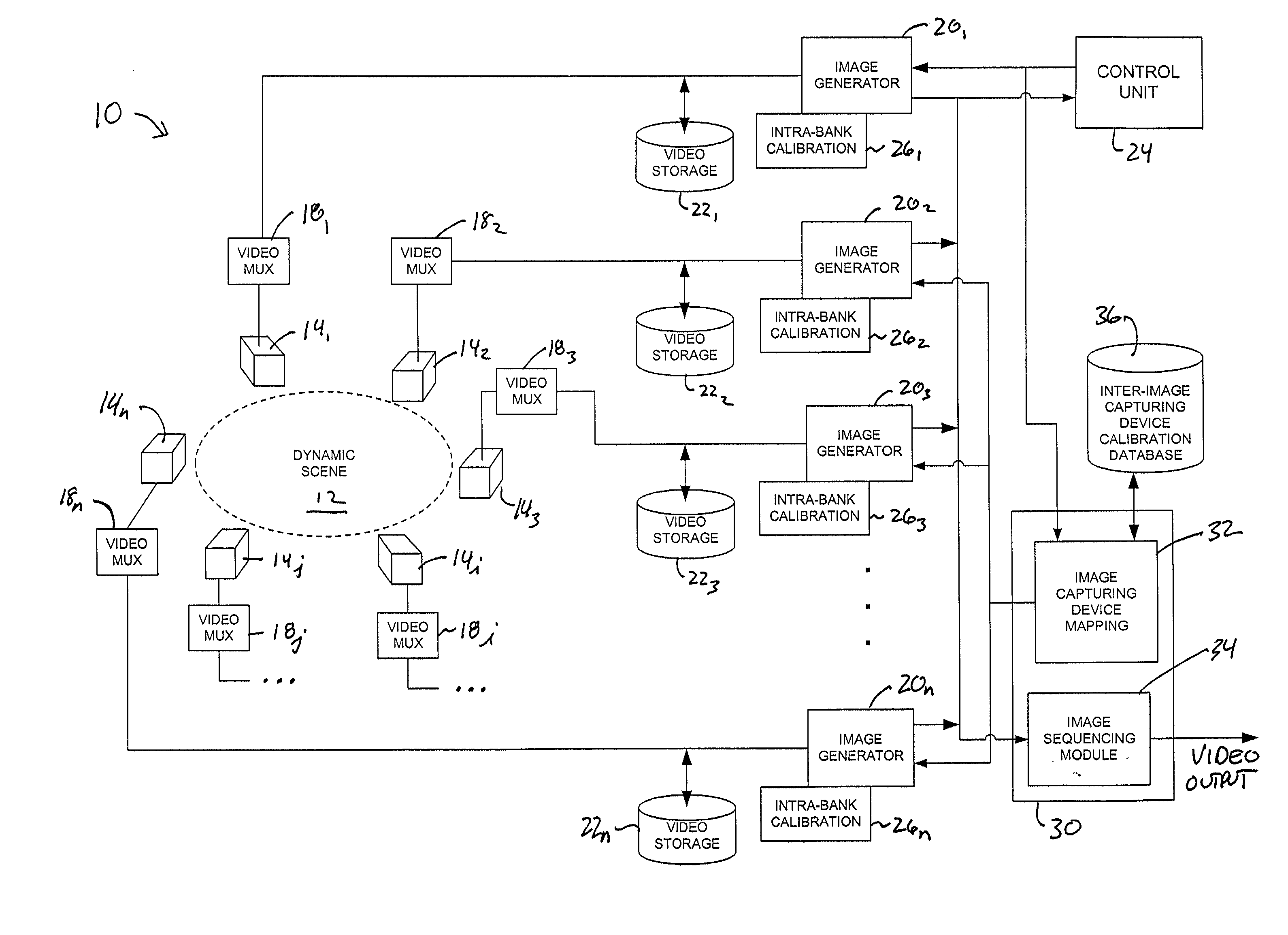
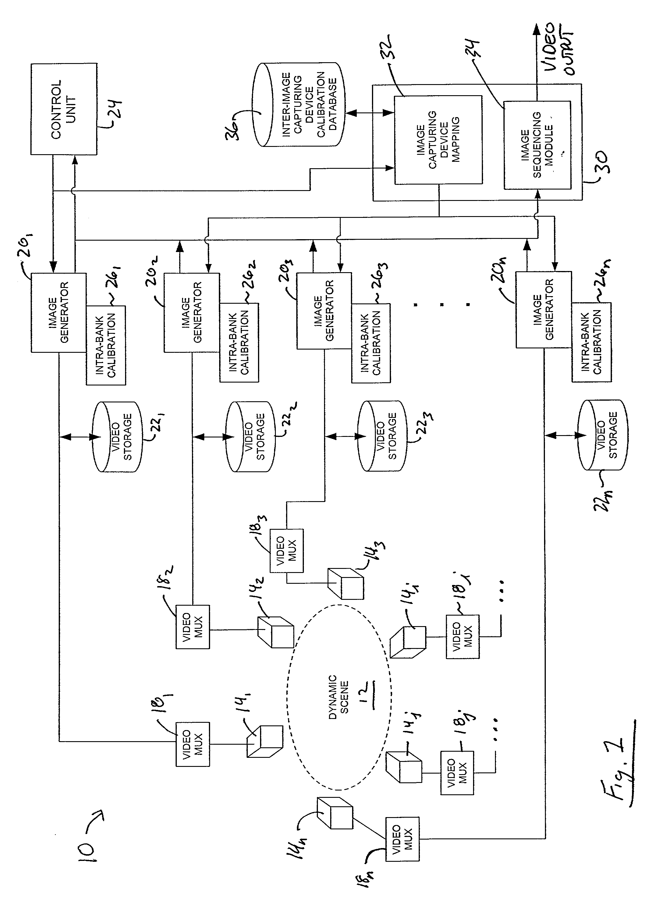
[0023] FIG. 1 is a diagram of a system 10 for obtaining video of multiple moving fixation points within a dynamic scene 12 according to one embodiment of the present invention. The system 10 includes a number of static (i.e., non-moving) image capturing devices 14.sub.1-n ...


PUM


Abstract

A system and method for obtaining video of a moving fixation point within a scene. According to one embodiment, the system includes a control unit and a plurality of non-moving image capturing devices positioned around the scene, wherein the scene is within a field of view of each image capturing device. The system also includes a plurality of image generators, wherein each image generator is in communication with one of the image capturing devices, and wherein a first of the image generators is responsive to a command from the control unit. The system also includes a surround-view image sequence generator in communication with each of the image generators and responsive to the command from the control unit for generating a surround-view video sequence of the fixation point within the scene based on output from certain of the image generators.

Description

BACKGROUND OF INVENTION[0001] 1. Field of Invention[0002] The present invention relates generally to image processing and, more particularly, to systems and methods for obtaining video of multiple moving fixation points within a dynamic scene.[0003] 2. Description of the Background[0004] In video applications, it is often desirable to separately take a set of images of a spot of action, called a fixation point, with a number of cameras surrounding the fixation point. From these sets of images one can create a so-called "3D surround-view" image sequence, which will make viewers feel as if they are flying around the scenes they see. Such image sequences are also sometimes referred to as a "3D fly-around" image sequence and "spin-image" sequence. This type of display heightens the viewer's ability to perceive the 3D spatial relationships between objects in the scene.[0005] Initial systems to produce the "3D surround-view" effect were composed of several stationary cameras pointed at a ...

Claims


Application Information

Patent Timeline
IPC IPC(8): G06T15/20
CPCH04N5/2627G06T15/20
Inventor KANADE, TAKEOAMIDI, OMEADCOLLINS, ROBERT
Owner CARNEGIE MELLON UNIV
Why Eureka
Try Eureka