Pipe joint assembly

Inactive Publication Date: 2003-05-15
BAUGHMAN TILE
View PDF0 Cites 17 Cited by
  • Summary
  • Abstract
  • Description
  • Claims
  • Application Information

AI Technical Summary

Problems solved by technology

Furthermore, the coupling does not have a smooth interior surface which may cause interruption and turbulence in fluids as they pass through the coupling.
The joint created in Goddard, however, is not particularly strong, as the female portion is a single wall construction having corrugations that are many times smaller than the corrugations of the male portion.
Another disadvantage of the Goddard reference is that the formation of the male and female portions within a section of pipe increases the time it take to produce

Method used


Image

  • Pipe joint assembly
  • Pipe joint assembly
  • Pipe joint assembly

Examples


Embodiment Construction

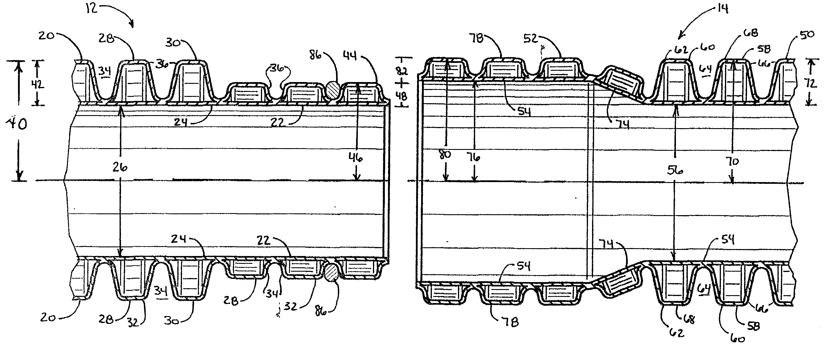
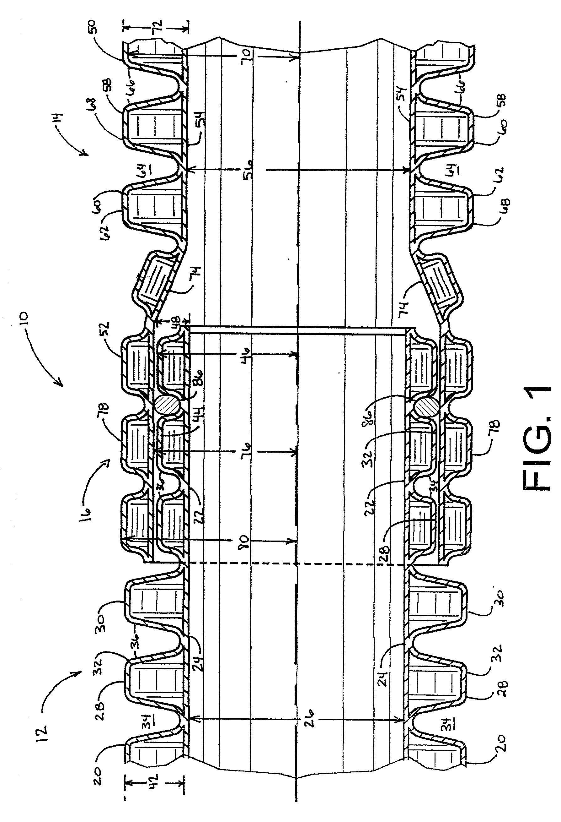
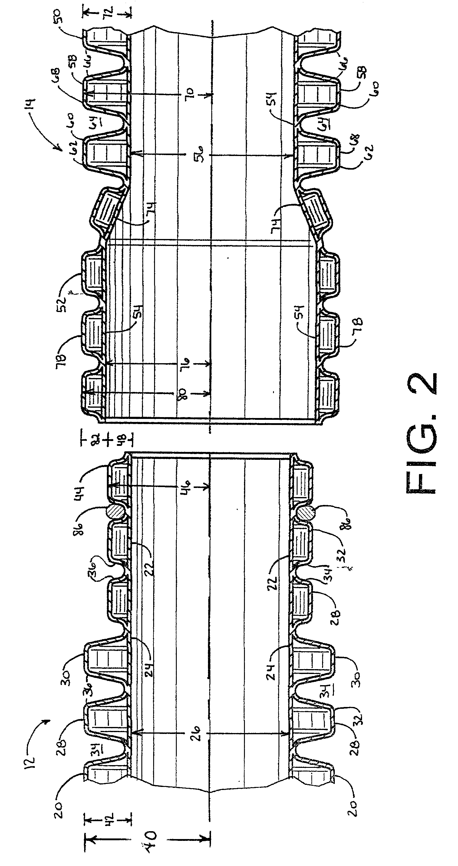
[0020] It is to be understood that the specific structures and processes illustrated in the attached drawings and described in the following description are simply exemplary embodiments of the inventive concepts defined in the appended claims. Hence, specific dimensions and other physical characteristics relating to the embodiments disclosed herein should not be considered as limiting, unless the claims expressly state otherwise.

[0021] Referring now to the drawings, FIG. 1 depicts a pipe joint assembly 10 having a first pipe section 12, a second pipe section 14 and a joint 16 defined therebetween. The pipe joint assembly 10 can be constructed substantially of polyethylene, however, other materials known by those skilled in the art, such as polyvinylchoride, polypropylene or other polyolefins, are within the scope and spirit of this invention.

[0022] In a preferred embodiment, the pipe joint assembly 10 has an overall outside diameter 18. The outside diameter 18 is substantially const...


PUM


Abstract

A pipe joint assembly joins two double wall pipe sections together. The pipe joint assembly includes a first pipe section having at least one double wall corrugation on an end portion, a second pipe section having at least one double wall corrugation on an end portion and a joint formed by locating the first pipe section end portion and the second pipe section end portion in an overlapping relationship. The pipe joint assembly substantially increases the strength of the joint relative to conventional pipe assemblies.

Description

[0001] 1. Field of the Invention[0002] The present invention relates to a pipe joint assembly. More particularly, the present invention relates to a pipe joint assembly for joining two double wall pipe sections. Most particularly, the present invention relates to a pipe joint assembly for joining first and second pipe sections having double wall corrugations with a joint formed from the first and second sections.[0003] 2. Discussion of the Related Art[0004] In the related art, there are essentially two methods for joining two corrugated pipes together. The first method is represented in U.S. Pat. No. 4,795,197 to Kaminski et al. In Kaminski, two corrugated pipes are joined by locating the end portions of the pipes within a common sleeve. The sleeve attaches to the outside surfaces of both end portions. The sleeve increases the outside diameter of the resulting length of pipe thereby requiring additional clearance or digging around the coupling to accommodate it in a trench. Furtherm...

Claims


Application Information

Patent Timeline
IPC IPC(8): F16L25/00F16L39/00
CPCF16L25/0045F16L39/005F16L25/0063
Inventor BAUGHMAN, BRADLINSGESEDER, HELMUT
Owner BAUGHMAN TILE
Why Eureka
Try Eureka