Control method and apparatus of screw fastening apparatus

a control method and screw technology, applied in the direction of wrenches, derricks/masts, manufacturing tools, etc., can solve the problems of the apparatus not being suitable for fastening a screw with high precision, the reaction of the operator becomes a and the load acting on the operator is grea

Inactive Publication Date: 2003-05-15
ESTIC CORP
View PDF0 Cites 50 Cited by
  • Summary
  • Abstract
  • Description
  • Claims
  • Application Information

AI Technical Summary

Problems solved by technology

Therefore, as the fastening torque is increased, there is a problem that its reaction becomes a load acting on the operator.
In the case of the above-mentioned apparatus whose shaft rotates continuously, since the reaction force of the fastening torque is received by the operator's hand directly, the load acting on the operator is great.
In the conventional impact type screw fastening apparatus, however, since a screw is fastened through a collision energy generating mechanism and a socket, precision of the fastening torque is largely varied depending upon variation of transmitting efficiency of these members, and this apparatus is not suitable for fastening a screw with high precision.
(1) In order to control the fastening torque, it is necessary to adjust a hydraulic pressure of the bypass valve functioning as the clutch mechanism, but the hydraulic pressure must be adjusted whenever the target torque is changed.
(2) The oil pulse generating section is a mechanism for generating the impulse by compressing and decompressing the oil while rotating. Therefore, oil and constituent parts such as a compression blade are deteriorated and worn as being used. Thus, it is necessary to frequently readjust and replace the parts.
(3) Since the characteristics of the oil pulse wrench are varied depending upon an oil temperature also, there is a possibility that the precision of the fastening torque and ability of fastening step is varied.
(4) A heat radiation of the oil pulse section is great due to repetition of compression and decompression of oil. Therefore, the pulse generating mechanism is cooled utilizing emission of an air motor. For this reason, if the pulse generating mechanism is not cooled, its temperature is increased up to approximately 100.degree. C. for some minutes' operation. Thus, there is a possibility that problems occur with respect to safety and stability of the function.
(5) For the above reasons, in the case of the oil pulse wrench, the necessity of using an air motor as a driving source is high and flexibility in selection of the driving source is low. Incidentally, an air motor has low energy efficiency as compared with an electric motor, and has a problem of dust and mist.

Method used


Image

  • Control method and apparatus of screw fastening apparatus
  • Control method and apparatus of screw fastening apparatus
  • Control method and apparatus of screw fastening apparatus

Examples


Embodiment Construction

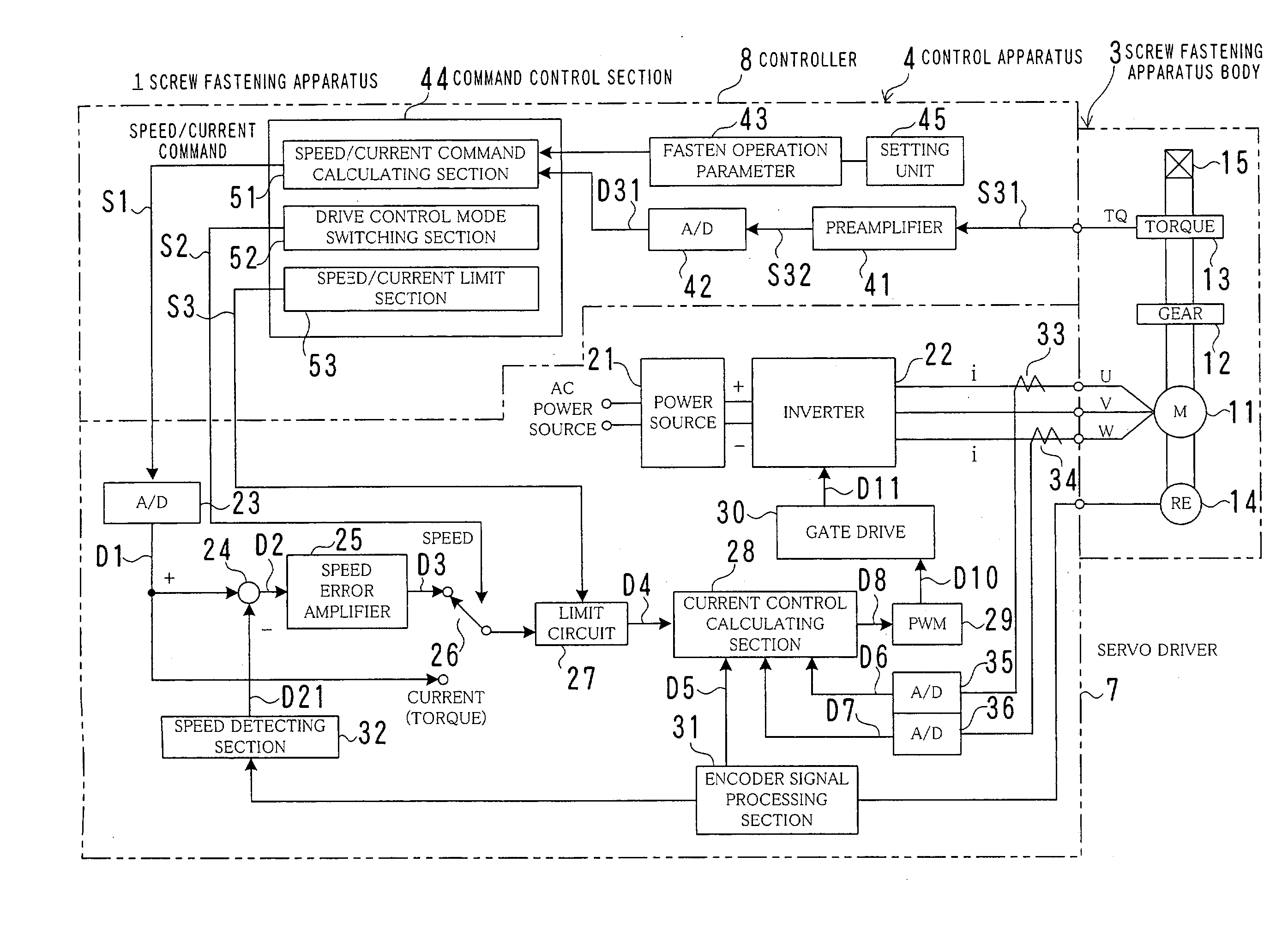
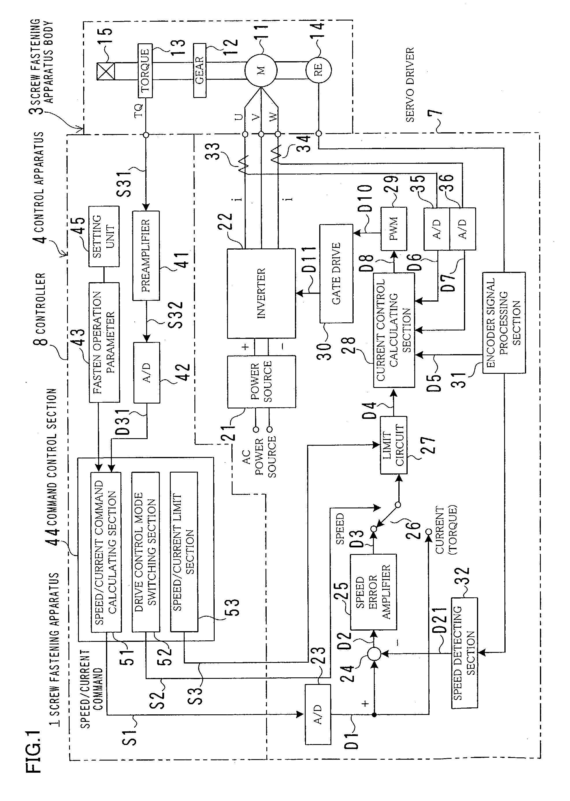
[0029] FIG. 1 is a block diagram showing the entire structure of a screw fastening apparatus 1 of the present invention.

[0030] In FIG. 1, the screw fastening apparatus 1 includes a screw fastening apparatus body 3, and a control apparatus 4 having a servo driver 7 and a controller 8.

[0031] The screw fastening apparatus body 3 includes a motor 11, a deceleration gear 12, a torque sensor 13, an encoder 14, an output shaft 15, a casing (not shown), switches (not shown) and the like.

[0032] The motor 11 is a three-phase AC servomotor and is a rotation driving source for rotating and driving the output shaft 15 through the deceleration gear 12.

[0033] The deceleration gear 12 decelerates the rotation of the motor 11 and a planetary gear is used for example.

[0034] The torque sensor 13 detects a screw fastening torque TQ by the motor 11 and outputs a detection signal S31. In this embodiment, the torque sensor 13 is directly connected to the output shaft 15 so that a torque generated in the o...


PUM


Abstract

It is an object of the present invention to overcome various drawbacks of a conventional oil pulse wrench by using an electric motor, to reduce a reaction force and to fasten a screw with high precision. To achieve the object, the invention provides a control method of a screw fastening apparatus using an electric motor as a rotation driving source, the method comprising the steps of; intermittently supplying current pulse DP to the motor, detecting an actual torque at predetermined time intervals, maintaining a current value when a detected torque value does not exceed a maximum value of past detected torques value and increasing the current value by a predetermined amount when the detected torque value exceeds the maximum value of the past detected torque value, and stopping the supply of the current pulse DP when the detected torque value reaches a target value TQJ.

Description

[0001] The present invention relates to a control method and a control apparatus of a screw fastening apparatus, and more particularly, to a screw fastening apparatus whose reaction force is reduced so that the screw fastening apparatus can be held by one hand.DESCRIPTION OF THE PRIOR ART[0002] Conventionally, a power-assisted screw fastening apparatus is used for fastening a bolt or a screw with a predetermined torque. A screw fastening apparatus is generally controlled such that its shaft is continuously rotated to fasten a screw and when the torque reaches a certain value, the power is cut off or a clutch is slid.[0003] Meanwhile, an operator holds the screw fastening apparatus with his / her hand for fastening a screw with respect to a work on a conveyer in various assembly lines in many cases.[0004] In such a case, it is desired that the screw fastening apparatus can be held with one hand in view of operability. In the case of a one-handed type screw fastening apparatus, reaction...

Claims


Application Information

Patent Timeline
Patent Type & Authority Applications(United States)
IPC IPC(8): B25B23/14B25B23/147
CPCB25B23/1405B25B21/02Y10S388/937B25B23/1475
Inventor ITO, TAKAYA
Owner ESTIC CORP
Why Eureka
Try Eureka