Headphone

Inactive Publication Date: 2003-05-15
SONY CORP
View PDF0 Cites 18 Cited by
  • Summary
  • Abstract
  • Description
  • Claims
  • Application Information

AI Technical Summary

Benefits of technology

0010] The object of the present invention is to provide a neckband type h

Problems solved by technology

If this type of gap occurs, there is a chance that the band may be pressed forward and the headphone units shift and fall from the ears when, for example, the wearer leans on a chair or wall and is not preferred.
It is not impossible to provide an adjustment mechanism to make it possible to adjust the size of the band although a band mechanism is complicated and the design of the headphone de

Method used


Image

  • Headphone
  • Headphone
  • Headphone

Examples


first embodiment

[0042] In the following, the present invention will be described with reference to FIG. 4 to FIG. 11.

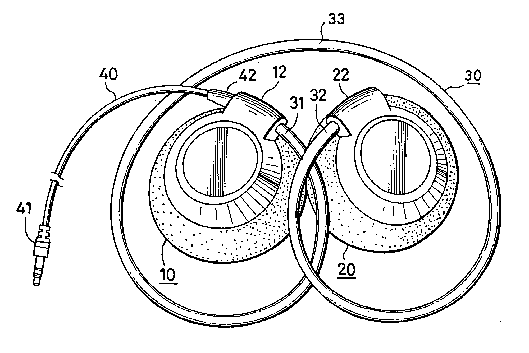
[0043] FIG. 4 and FIG. 5 are plan views which show the headphone device according to this embodiment. These FIGS. 4, 5 show the headphone device in a stored state. FIG. 4 shows the shape of the surface (the surface here is the surface where the audio output surface changes to the rear). FIG. 5 shows the shape of the rear surface (audio output surface). As shown in FIGS. 4 and 5, the headphone device of this example has a shape wherein the left-side speaker unit 10 and the right-side speaker unit 20 are connected by a band 30 that is wound in a circular shape. The band 30 is comprised of a material with elasticity and has a property which allow it to be extended almost straight from a state in which it is wound in a circular shape.

[0044] As an example of the composition of the band 30, a metal wire rod that has elasticity and a signal line that transfers audio signals are passed throu...

second embodiment

[0073] By means of using the headphone device of the second embodiment in this manner, the headphone device can be reduced in size even more when stored making it for example, easy to carry.

[0074] Next, a third embodiment of the present invention will be described referring to FIG. 15 to FIG. 17. The headphone device of the third embodiment of the present invention uses a vertical-in-the-ear type format for the headphone unit (hereinafter referred to as vertical type). For this vertical type the audio output surface inside the headphone unit is worn perpendicular to the opening of the ear.

third embodiment

[0075] FIG. 15 is a top plan view that shows the headphone device according to the FIG. 15 shows the shape of the front of the headphone device when stored. The headphone device of this example uses the above-mentioned vertical type for the left-side speaker unit 110 and the right-side speaker unit 120. The drivers incorporated inside the speaker units 110, 120 have comparatively small diameters of approximately 16 mm. The use of small drivers makes it possible to have a shape that allows the end of the unit to be slightly inserted into the opening of the ear of the wearer. The housings that comprise the speaker units 110, 120 is formed of a resin.

[0076] The band 130 used in this example uses a band with a shape identical to the band 30 described in the first embodiment and is wound approximately 650.degree. (namely, about {fraction (7 / 4)} of a turn). The band 130 is comprised of a material with elasticity and has properties which allow it to be extended from a state in which it is...


PUM


Abstract

In a neckband type headphone device there is provided a band onto which speaker units are connected to both ends thereof. These speaker units are worn on the left and right ears. The band has a shape wherein the area close to the connecting part between both speaker units forms a curve and passes above or below the ears of the listener when it is wound in a circular shape and extended. The band is formed from an elastic material into a shape that presses down at the approximate center on the rear of the head of the listen

Description

[0001] The present invention relates to a headphone device for listening to audio or sound by connecting to the source of audio signals. In particular, the present invention relates to a headphone device that can be made smaller in size when not worn.[0002] Conventionally, a device that is positioned on a band and hangs on the rear of the head from both ears of the listener has been practically used as a headphone device. This type of headphone device is referred to as a neckband type because the band is positioned on the rear of the head slightly above the neck at the rear of the head.[0003] FIG. 1 is a perspective view that shows an example of a neckband type headphone device that is currently in the market. For this headphone device a left-side speaker unit 1 and a right-side speaker unit 2, which incorporate therein driver units with diameters of a few centimeters, are connected by an almost semicircular band 3.[0004] An earpad is attached to the inside of each of speaker units ...

Claims


Application Information

Patent Timeline
IPC IPC(8): H04R1/10H04R5/033
CPCH04R5/0335H04R1/1008H04R1/10
Inventor ITO, TOMOHIROTSUNODA, NAOTAKAHAMADA, TOMOMI
Owner SONY CORP
Why Eureka
Try Eureka