Liquid dispensing pump system

a pump system and liquid technology, applied in the direction of machines/engines, liquid fuel engines, positive displacement liquid engines, etc., can solve the problem of design problems that have been found unsatisfactory for applications

Inactive Publication Date: 2003-05-15
FLUID MANAGEMENT LLC
View PDF0 Cites 32 Cited by
  • Summary
  • Abstract
  • Description
  • Claims
  • Application Information

AI Technical Summary

Benefits of technology

0033] It should be understood that the drawings are not necessarily to scale and that embodiments are sometimes illustrated by graphic symbols, phantom lines, diagrammatic representations and fragmentary views. In certain instances, details which are not necessary for an understa...

Problems solved by technology

Further, there is typically a gap between the distal ends of the rotor teeth and the head plate or casing cover which permits migration of fluid from the inlet port to an area disposed between the head plate and the idler.
However, while the head design disclos...

Method used


Image

  • Liquid dispensing pump system
  • Liquid dispensing pump system
  • Liquid dispensing pump system

Examples


Embodiment Construction

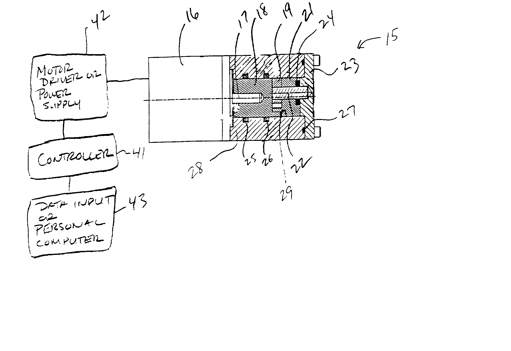
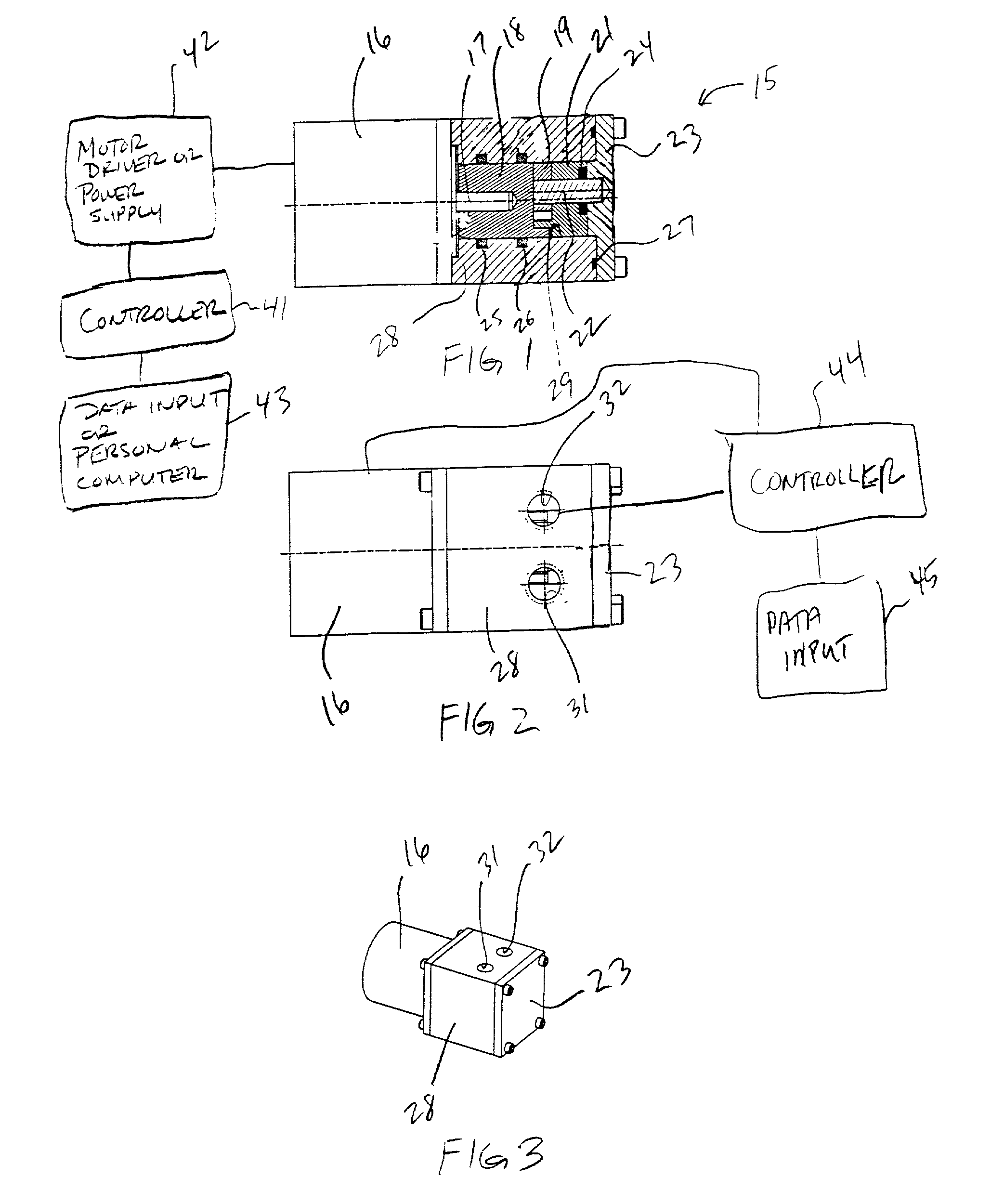
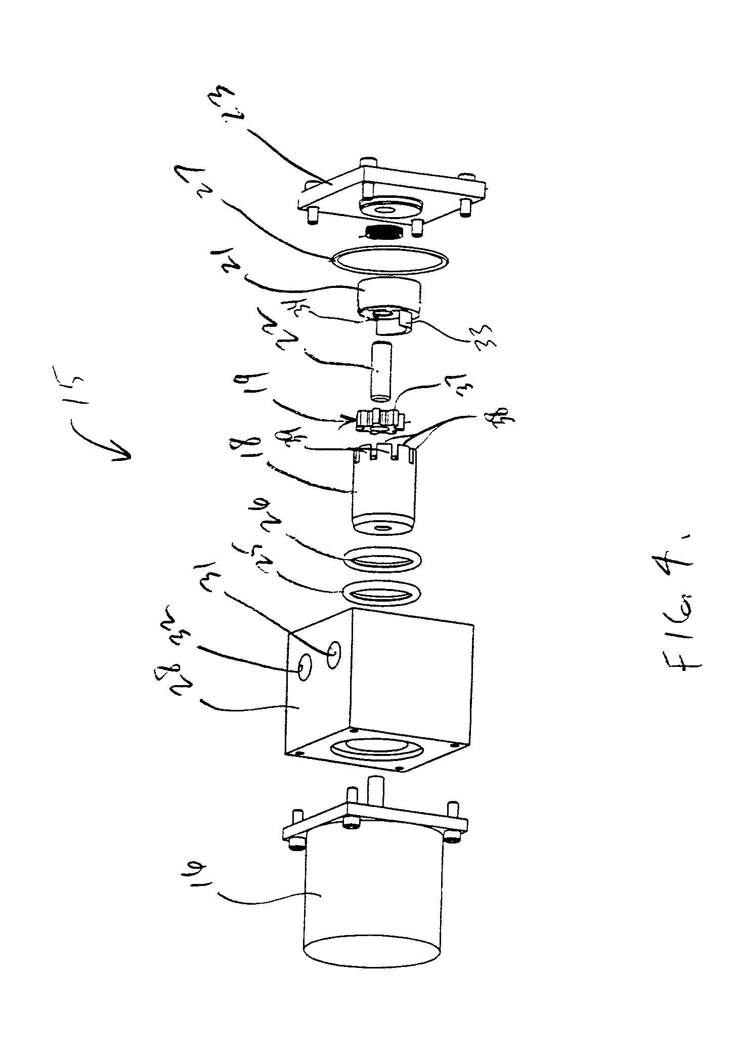
[0034] Turning to FIGS. 1-4, one embodiment of an improved gear pump 15 is disclosed. The pump 15 includes a stepper motor 16 coupled to a drive shaft 17. The drive shaft 17 is received in a rotor 18. The rotor 18 is meshed with an idler 19 that is mounted to a head 21 by way of an idler pin 22. The idler pin extends through the head 21 into the head cover plate 23. The head 21 is biased toward the rotor 18 by a wave spring 24. Seals are illustrated at 25-27. The casing 28 and head plate 23 define a pump chamber 29 which accommodates the rotor 18, idler 19 and head 21. An input port 31 and an output port 32 are shown in FIG. 2. In the internal gear pump design disclosed herein, the input and output ports are interchangeable. Further, one advantage of the disclosed design is that the input and output ports 31, 32 can be disposed in a variety of locations on the casing 28.

[0035] As best seen in FIG. 5, the head 21 includes a crescent 33 and an aperture 34 for accommodating the idler p...


PUM


Abstract

An internal gear pump including a stepper motor coupled to a drive shaft that is coupled to a rotor and meshed with an idler is disclosed. A controller is linked to the stepper motor. The stepper motor imparts a stepped rotational movement to the drive shaft wherein a single 360° rotation of the drive shaft comprises a plurality of steps. The controller sends a signal to the stepper motor to rotate the drive shaft a predetermined number of steps, based upon an inputted dispense amount. The signal causes the stepper motor to rotate the drive shaft a predetermined number of steps. The controller calculates the predetermined number of steps based upon the inputted dispense amount using an algorithm that is derived experimentally that defines a relationship between dispense amount and the number of steps required for each dispense amount. The algorithm is unique for each fluid to be pumped. A head surface area that is planar with the exception of an aperture for receiving the idler pin and a crescent is provided for increased accuracy.

Description

[0001] 1. Technical Field[0002] An improved internal gear pump is disclosed. More specifically, one disclosed internal gear pump includes a controller linked to a stepper motor for enhanced dispensing accuracy. Still another disclosed internal gear pump includes an improved head design for enhanced accuracy. Further, algorithms for providing precise pump control and dispensing accuracy are also disclosed.[0003] Internal gear pumps are known and have long been used for the pumping of thin liquids at relatively high speeds. The typical internal gear pump design includes a rotor mounted to a drive shaft. The rotor includes a plurality of circumferentially disposed and spaced apart rotor teeth that extend axially toward an open end of the pump casing. The open end of the pump casing is typically covered by a head plate or cover plate which, in turn, is connected to an idler. The idler is mounted to the head plate eccentrically with respect to the rotor teeth. The idler also includes a p...

Claims


Application Information

Patent Timeline
IPC IPC(8): F04C2/10F04C11/00F04C14/08F04C15/00
CPCF04C11/00F04C2/101F04C15/008F04C14/08
Inventor BUSH, MATTHEW D.KOTH, HOWARD E.CRAWFORD, MICHAEL R.
Owner FLUID MANAGEMENT LLC
Why Eureka
Try Eureka