
Boring head, roller cutter and saddle for a boring head for rotary drilling

a technology of boring head and roller cutter, which is applied in the direction of shaft sinking, cutting machines, shaft equipment, etc., can solve the problem of breaking one shaft spigot of each roller cutter, and achieve the effect of prolonging production periods

Inactive Publication Date: 2003-06-12
SANDVIK INTELLECTUAL PROPERTY AB
View PDF7 Cites 0 Cited by
  • Summary
  • Abstract
  • Description
  • Claims
  • Application Information

AI Technical Summary

Benefits of technology

[0004] One object of the present invention is to provide a boring head and a roller cutter and a saddle, the designs of which assist in obtaining longer production periods.
[0005] Another object of the present invention is to provide a durable roller cutter. Still another object of the present invention is to provide a roller cutter and a saddle, the designs of which prevent loosening relative to each other.

Problems solved by technology

The great drilling forces that influence the known boring head frequently break one shaft spigot of each roller cutter.

Method used


Image

  • Boring head, roller cutter and saddle for a boring head for rotary drilling
  • Boring head, roller cutter and saddle for a boring head for rotary drilling
  • Boring head, roller cutter and saddle for a boring head for rotary drilling

Examples


Embodiment Construction

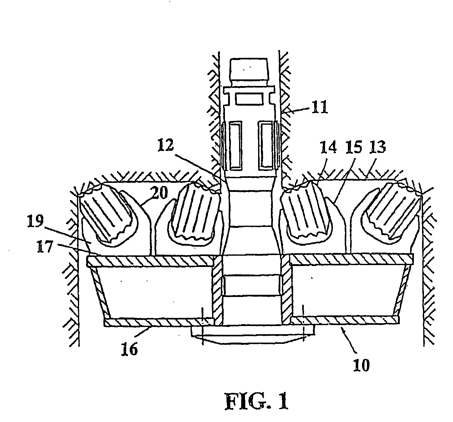
[0021] In FIG. 1 is shown how a pilot hole 11 is pre-drilled in a conventional manner between upper and lower levels, not shown, in a mine. The hole 11 is reamed by means of a reaming head depicted by the reference numeral 10. The reaming head 10 is attached to a drive stem 12 by means of which the reaming head is rotated and forced against an annular surface 13 which surrounds the pilot hole 11. The surface 13, thus, defines the face of the earth formation.

[0022] The invention generally relates to earth drilling, but is primarily intended for raise boring. During raise boring, a distance between the lower and the upper level of the mine is drilled in a mine to form a pilot hole, whereafter the pilot hole is reamed by means of a large diameter boring head.

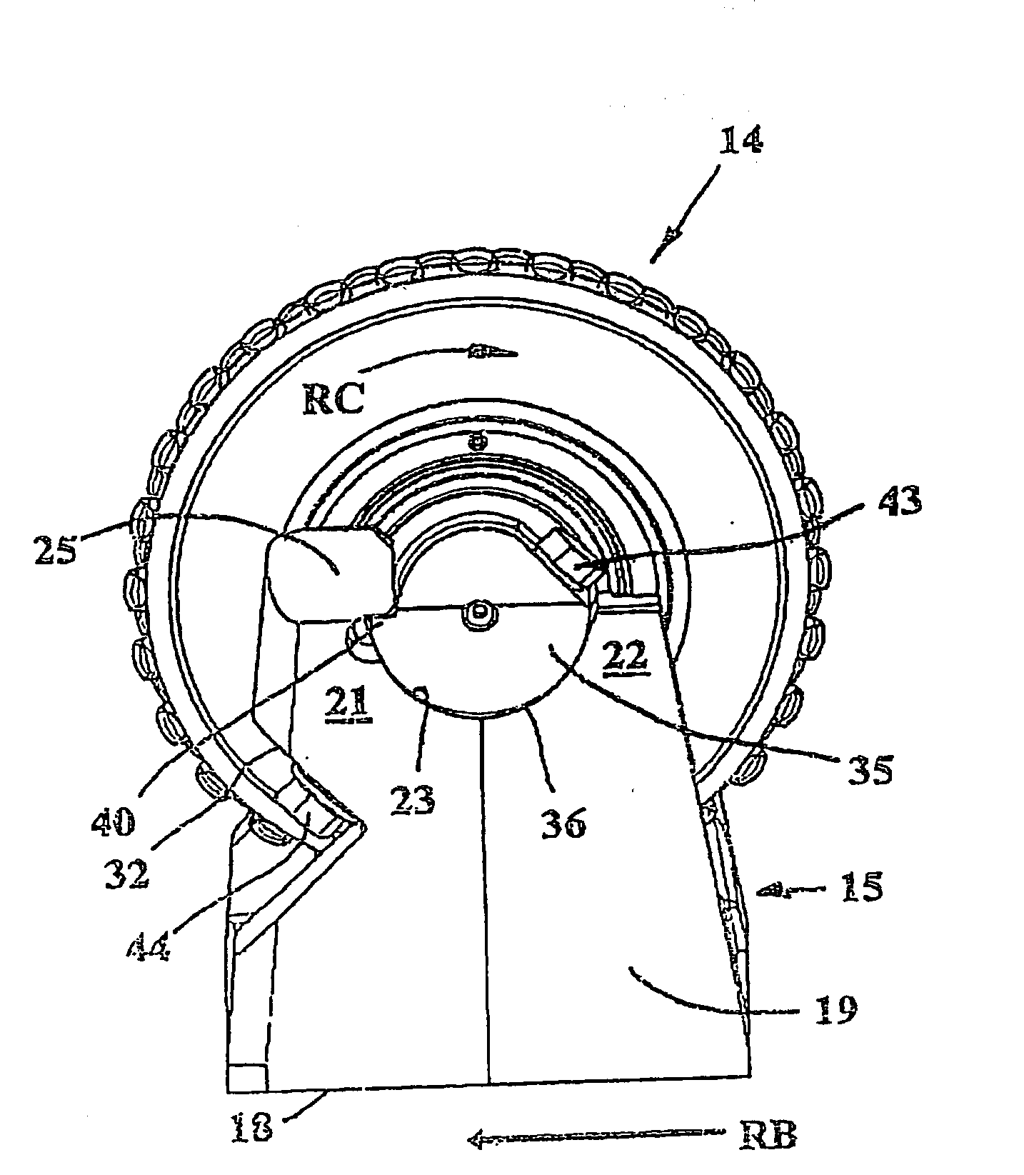
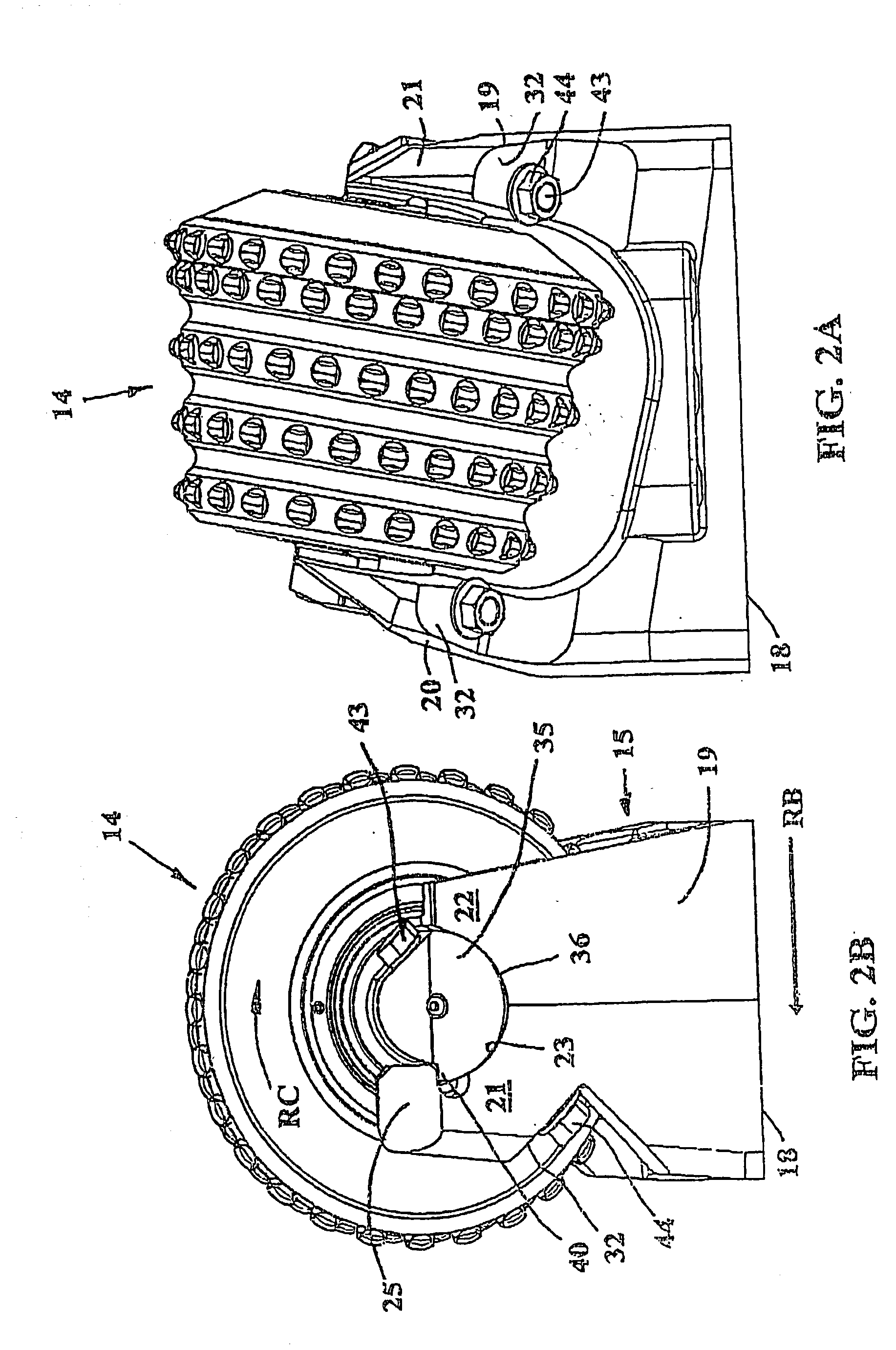
[0023] The boring head 10 comprises a main body 16 and a plurality of roller cutters or cutters 14, which are mounted on the main body in attachments or saddles 15. Each roller cutter comprises a rotary body 14a carrying circumfere...


PUM


Abstract

A raise boring head includes a roller cutter body and a saddle intended for rotary drilling in earth and rock formations. The roller cutter body is rotatably journalled on a shaft that is provided with two shaft spigots at its opposite ends. Each spigot has a second support surface provided for cooperation with a first support surface of the saddle to hold the roller cutter to the saddle. Each shaft spigot is provided with a hole for receiving a fastener that also passes through the second support surface in order to connect the shaft spigot to the saddle. The first support surface and the second support surface are curved. The first support surface and the second support surface connect directly or indirectly to stop shoulders for counteracting rotation of the shaft. The fastener is eccentric to the shaft axis and arranged to press the stop surfaces together.

Description

[0001] This application claims priority under 35 U.S.C. .sctn.119 to Patent Application Serial No. 0104138-3 filed in Sweden on Dec. 10, 2001, the entire content of which is incorporated by reference.[0002] The present invention relates to a boring head and a roller cutter and a saddle for a boring head for rotary drilling of a front in earth and rock formations.PRIOR ART[0003] A roller cutter for a known boring head is held in a saddle via polygonal shaft spigots of the roller cutter, see for example Persson U.S. Pat. No. 4,448,271. The great drilling forces that influence the known boring head frequently break one shaft spigot of each roller cutter.OBJECTS OF THE INVENTION[0004] One object of the present invention is to provide a boring head and a roller cutter and a saddle, the designs of which assist in obtaining longer production periods.[0005] Another object of the present invention is to provide a durable roller cutter. Still another object of the present invention is to prov...

Claims


Application Information

Patent Timeline
Patent Type & Authority Applications(United States)
IPC IPC(8): E21B7/28E21B10/10E21B10/28
CPCE21B7/28E21B10/28E21B10/10
Inventor BROLUND, STIG-AKE
Owner SANDVIK INTELLECTUAL PROPERTY AB
Learn More