
Sealing ring for connecting two especially insertable concrete components

a technology of sealing ring and concrete, which is applied in the direction of engine sealing, sleeve/socket joint, shaping reinforcement, etc., can solve the problems of sealing ring moving on the mould ring during casting, sealing ring assuming incorrect fixing position in the socket, sealing ring compressing against the mould ring, etc., and achieves the effect of greater wall thickness

Inactive Publication Date: 2003-06-12
ASTRAZENECA AB
View PDF15 Cites 19 Cited by
  • Summary
  • Abstract
  • Description
  • Claims
  • Application Information

AI Technical Summary

Benefits of technology

[0008] Advantageously, the radial thickness of the sealing ring decreases across at least a portion of its cross-section so as to give the socket a greater wall thickness in its axially inner portion compared with its axially outer portion during said casting.

Problems solved by technology

One problem associated with prior-art sealing rings of this kind, i.e. sealing rings that are intended to be fixed in a concrete pipe socket in connection with the casting thereof, is that the sealing ring moves on the mould ring during casting.
Another problem associated with prior-art sealing rings of this kind is that, sometimes, the sealing ring is compressed against the mould ring as a result of the pressure exerted on the sealing ring by the concrete during casting.
Such compression may result in the sealing ring assuming an incorrect fixing position in the socket.
Another problem found in connection with prior-art sealing rings of this kind is that concrete will penetrate between the sealing ring and the mould ring during casting.
In many cases, this concrete will remain stuck to the sealing ring after the form stripping and will, of course, reduce the sealing effect of the sealing ring.
In prior-art sealing rings of this kind, the sealing ring, when being mounted on the mould ring, is stretched out in such a way that it tends to contract after the form stripping, which may lead to the sealing ring coming loose from the socket.
Another problem found when the annular gap that is to be sealed is small and the compression of the sealing ring is great is that fractures may develop in the socket.

Method used


Image

  • Sealing ring for connecting two especially insertable concrete components
  • Sealing ring for connecting two especially insertable concrete components
  • Sealing ring for connecting two especially insertable concrete components

Examples


Embodiment Construction

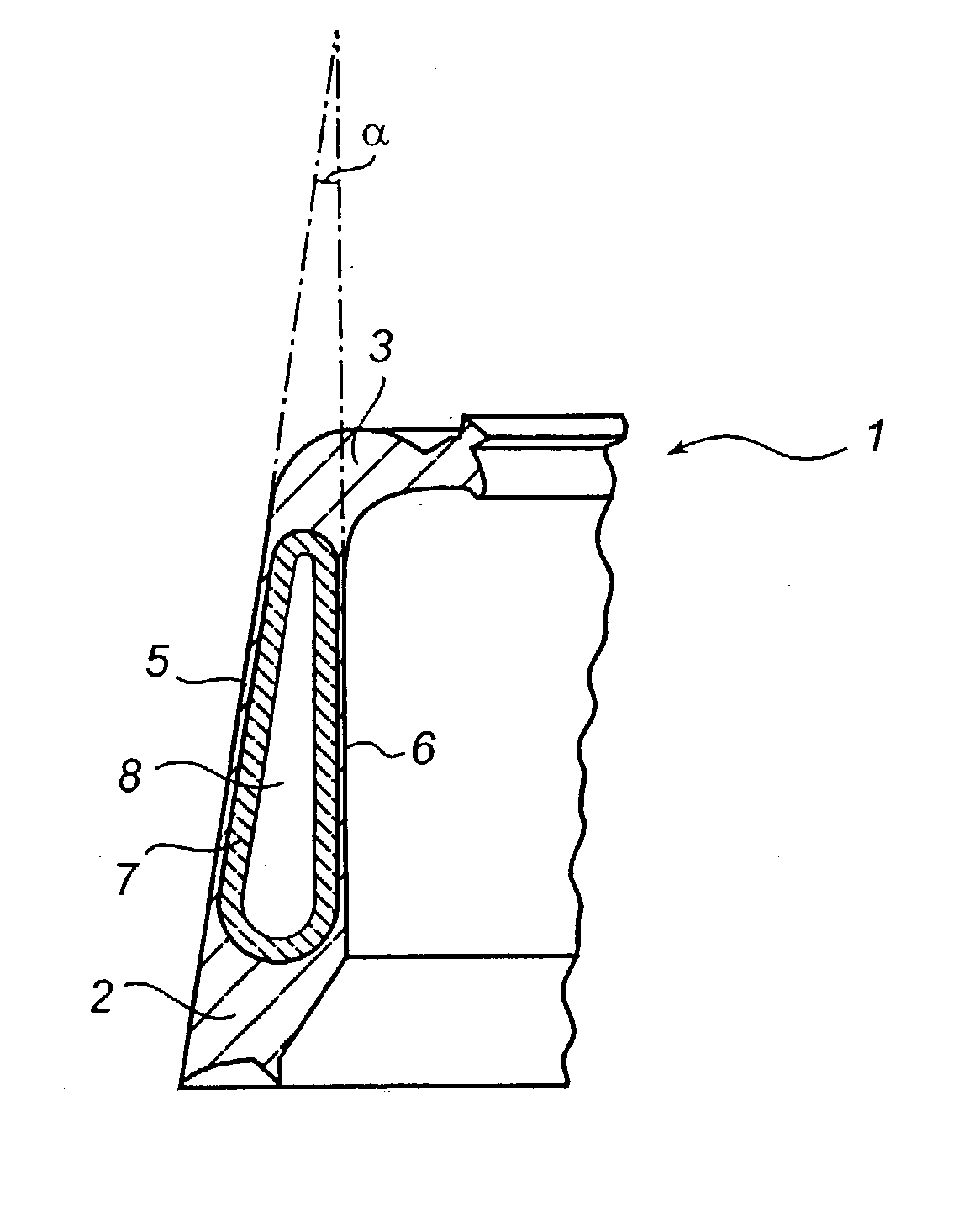
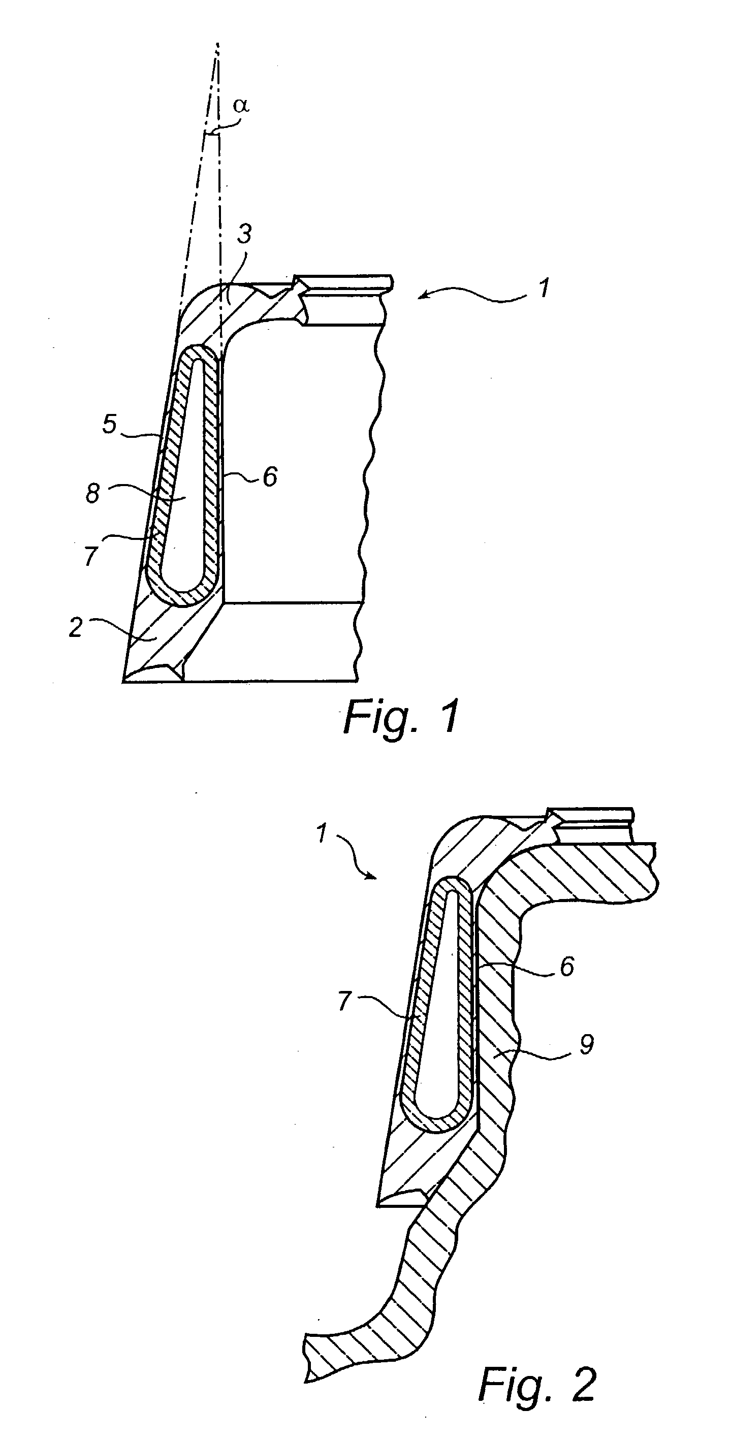
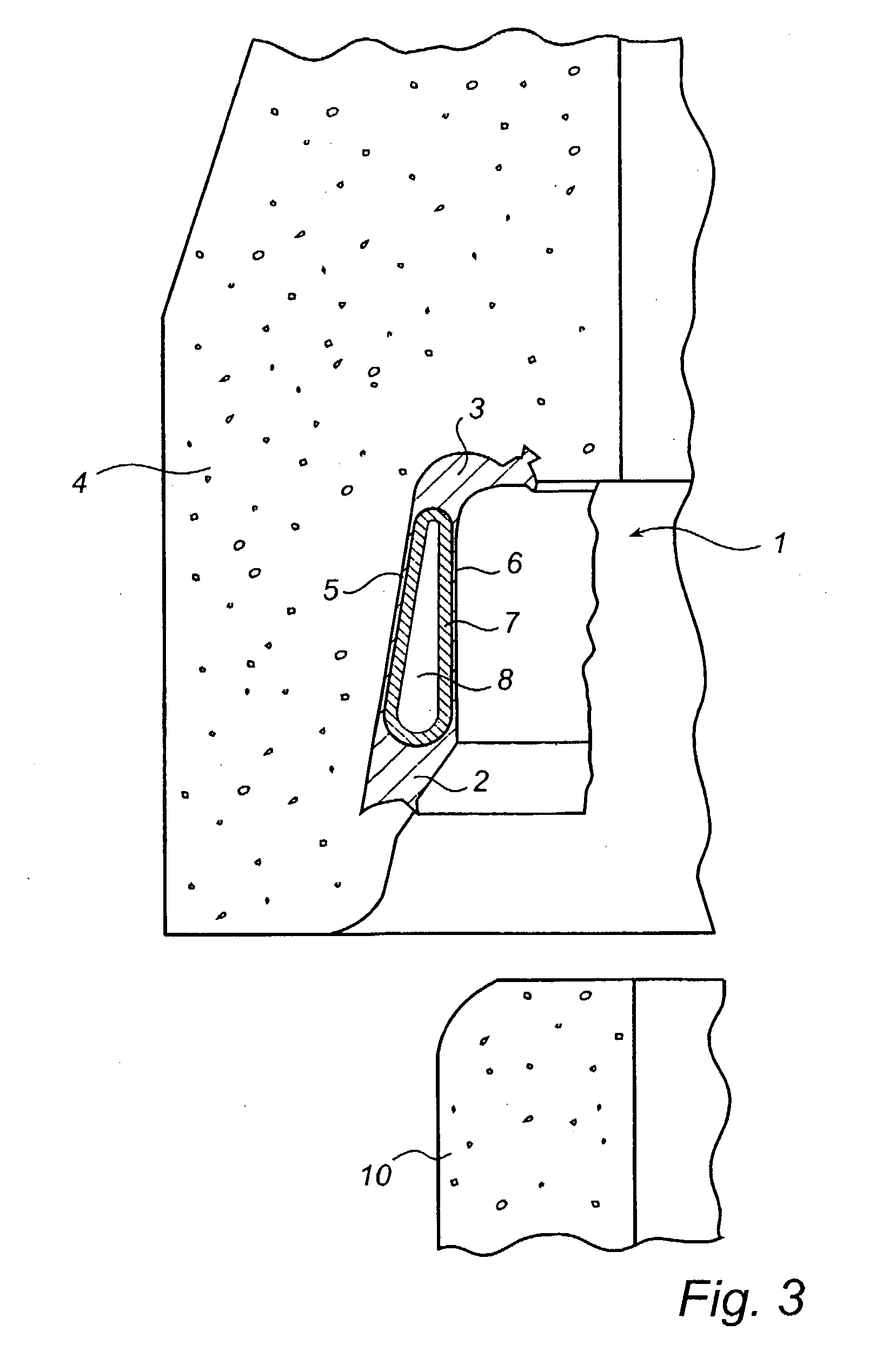
[0014] The sealing ring 1 shown in FIGS. 1-3 is made in one piece by means of co-extrusion of a soft rubber material with a hardness of 30-40 IRHD and a hard rubber material with a hardness of 60-80 IRHD. The soft rubber material and the hard rubber material are thus high-quality rubber materials, which according to various standard specifications may be used as sealing material.

[0015] The soft rubber material forms an axially outer sealing portion 2 and an axially inner sealing portion 3. In this connection, `axially outer` and `axially inner` refer to the location of the sealing ring 1 in a concrete pipe socket 4 (see FIG. 3). The soft rubber material further forms a radially outer sealing layer 5 and a radially inner sealing layer 6, which interconnect the portions 2 and 3 and which define, between them, a closed annular cavity, which is filled by a ring 7 of the hard rubber material. The ring 7 of hard rubber material is connected to the ring of soft rubber material formed by th...


PUM


Abstract

A scaling ring (1) for sealing an annular gap between a concrete pipe socket and a concrete pipe spigot end is adapted to be mounted on a mould ring intended for casting of a concrete pipe comprising a socket so as to be fixed in the socket by said casting. The scaling ring is made in one piece by means of co-extrusion of a soft rubber material and a hard rubber material. The soft rubber material has a hardness of 30-40 IRHD and forms a radially inner sealing layer (6), which is intended to abut against the mould ring during said casting and to abut sealingly against the spigot end during use of the sealing ring (1). The hard rubber material forms a second layer (7) located radially outside the radially inner sealing layer.

Description

FIELD OF THE INVENTION[0001] The present invention relates to a sealing ring for sealing an annular gap between a concrete pipe socket and a concrete pipe spigot end, said sealing ring being adapted to be mounted on a mould ring intended for casting of a concrete pipe comprising a socket so as to be fixed in the socket by said casting.BACKGROUND ART[0002] One problem associated with prior-art sealing rings of this kind, i.e. sealing rings that are intended to be fixed in a concrete pipe socket in connection with the casting thereof, is that the sealing ring moves on the mould ring during casting. Another problem associated with prior-art sealing rings of this kind is that, sometimes, the sealing ring is compressed against the mould ring as a result of the pressure exerted on the sealing ring by the concrete during casting. Such compression may result in the sealing ring assuming an incorrect fixing position in the socket. Another problem found in connection with prior-art sealing ri...

Claims


Application Information

Patent Timeline
IPC IPC(8): F16L21/03
CPCB28B21/563F16L21/03
Inventor BONNERT, ROGERHUNT, FRASERWILLIS, PAUL
Owner ASTRAZENECA AB
Learn More