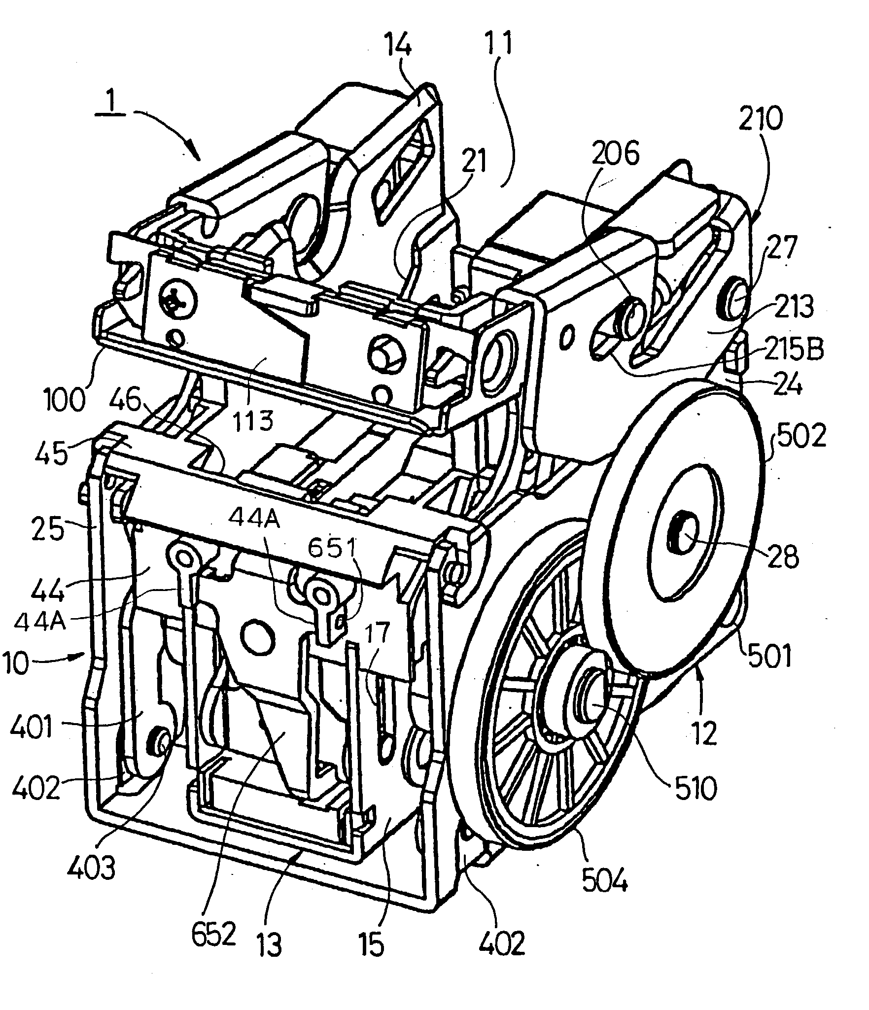
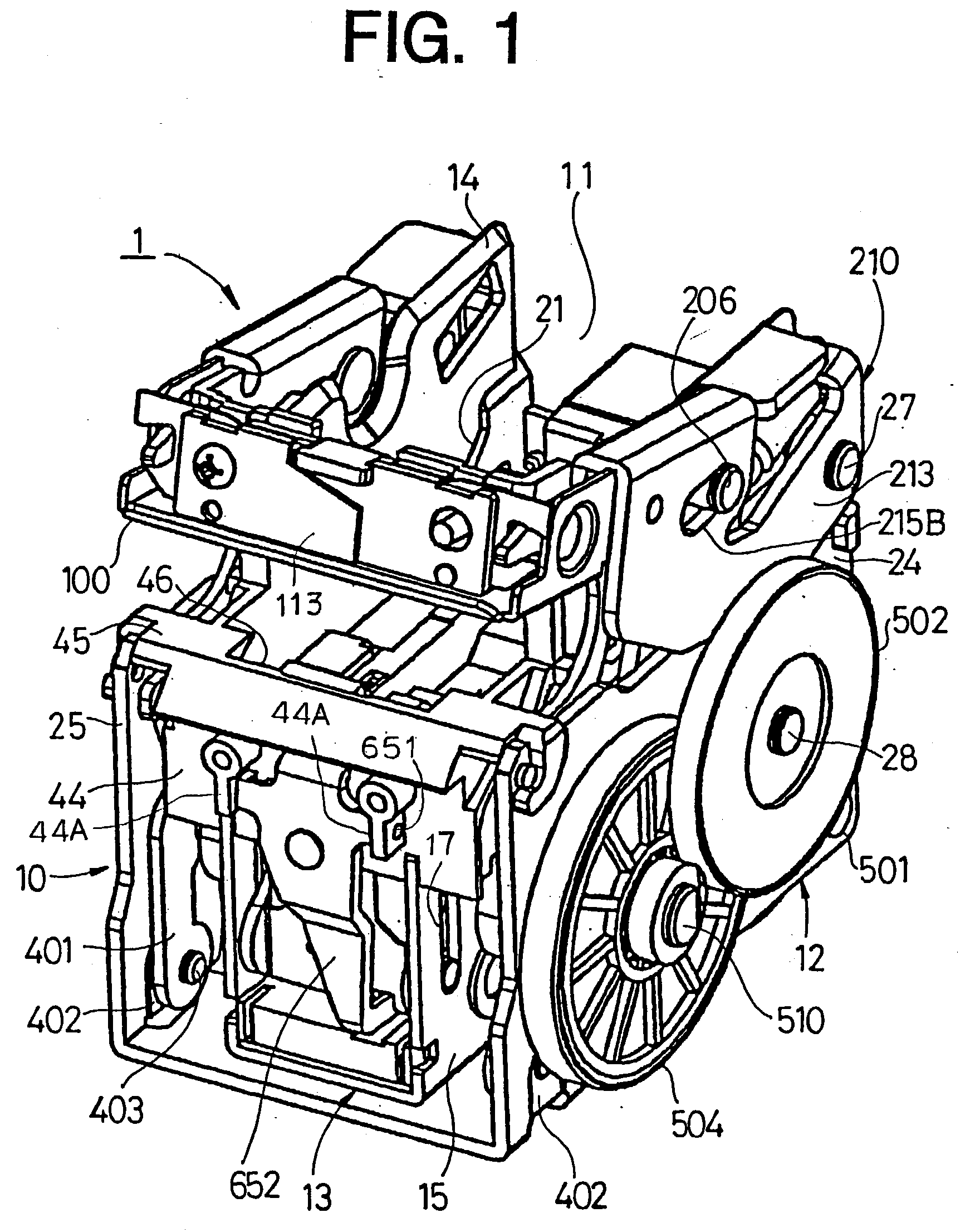
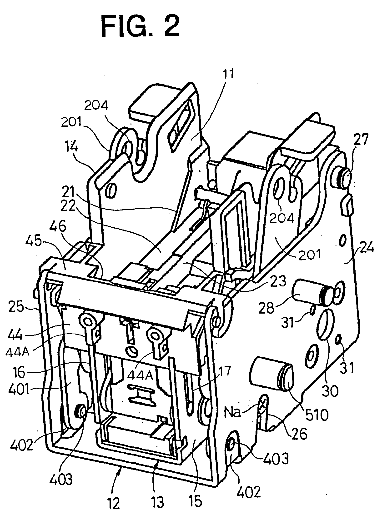
Motor-driven stapler
a motor-driven, stapler technology, applied in the direction of stapling tools, manufacturing tools, nailing tools, etc., can solve the problems of loud impact noise, malfunctioning sensor means for sensing the home position of the table,
- Summary
- Abstract
- Description
- Claims
- Application Information
AI Technical Summary
Benefits of technology
Problems solved by technology
Method used
Image
Examples
case 701
[0147] [Outer Case 701]
[0148] As shown in FIG. 36, the outer case 701 has openings 702, 703 formed at the back (on the right) and the upper portion thereof, and a holder portion 705 provided to be extended forwardly on the lower portion of a front wall portion 704. In addition, the outer case 701 has an opening on the lower portion thereof and a pair of spaced-apart side walls 706. On the inner sides of the side walls 706, formed are guide recessed portions 707, 708 that extend vertically. On the lower portions of the outer sides of the side walls 706, formed are projections 709 and recessed portions 710 at the positions corresponding to those of the guide recessed portions 708. Moreover, on the front wall portion 704, there is formed a window 713 that extends upwardly from the lower end of the front wall portion 704.
[0149] There is provided a guide plate 720 on the lower surface of the holder portion 705. The holder portion 705 is also provided with a pusher member 750 that is mova...
second embodiment
[0222] [Second Embodiment]
[0223] FIG. 62 is a view showing a feed mechanism 1000 according to a second embodiment. In this second embodiment, the inclined surface 922 of the pressing member 920 is provided with a recessed portion 940. The recessed portion 940 causes the pressing member 920 to move rearward against the biasing force of the feed spring 930 when the feed claw 910 submerges. The position of a point of action 920A acted from the feed claw 910 on the pressing member 920 is brought closer to the axial line 920J of the pressing member 920 as shown in FIG. 63. On the other hand, when the recessed portion 940 is not present, the point of action will sit on the lower portion 910A of the feed claw 910. The closer the point of action to the axial line 920J, the less the force for moving the pressing member 920 rearward becomes.
[0224] That is, a change in the position of the point of action will cause a change in submerging weight of the feed claw 910, and thus the submerging wei...
PUM
 Abstract
Description
Claims
Application Information
 - R&D
- Intellectual Property
- Life Sciences
- Materials
- Tech Scout
- Unparalleled Data Quality
- Higher Quality Content
- 60% Fewer Hallucinations
Browse by: Latest US Patents, China's latest patents, Technical Efficacy Thesaurus, Application Domain, Technology Topic, Popular Technical Reports.
© 2025 PatSnap. All rights reserved.Legal|Privacy policy|Modern Slavery Act Transparency Statement|Sitemap|About US| Contact US: help@patsnap.com


