Method for Producing a Bore

a technology of bores and machining methods, applied in the direction of manufacturing tools, instruments, electric digital data processing, etc., can solve the problems of high cost, large expenditure, and insufficient simulation of actual deformation state in operation, and achieve the effect of reducing expenditur

Inactive Publication Date: 2003-06-26
MASCHFAB GEHRING
View PDF0 Cites 10 Cited by
  • Summary
  • Abstract
  • Description
  • Claims
  • Application Information

AI Technical Summary

Benefits of technology

0006] It is an object of the present invention to provide a method of the aforementioned kind which enables th

Problems solved by technology

However, this method for manufacturing the bore causes a great expenditure as a result of the required devices.
This machining process r

Method used


Image

  • Method for Producing a Bore
  • Method for Producing a Bore

Examples


Embodiment Construction

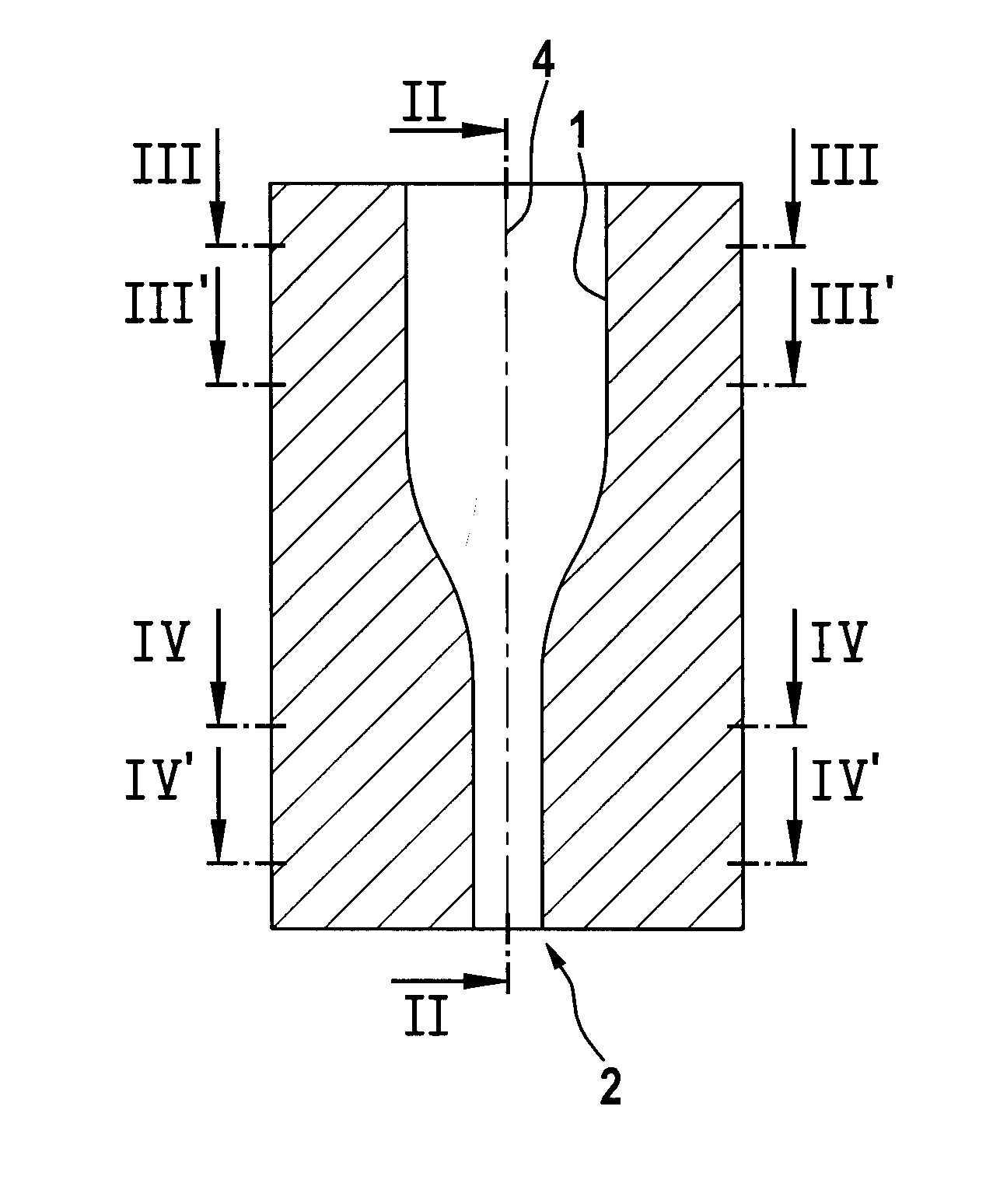
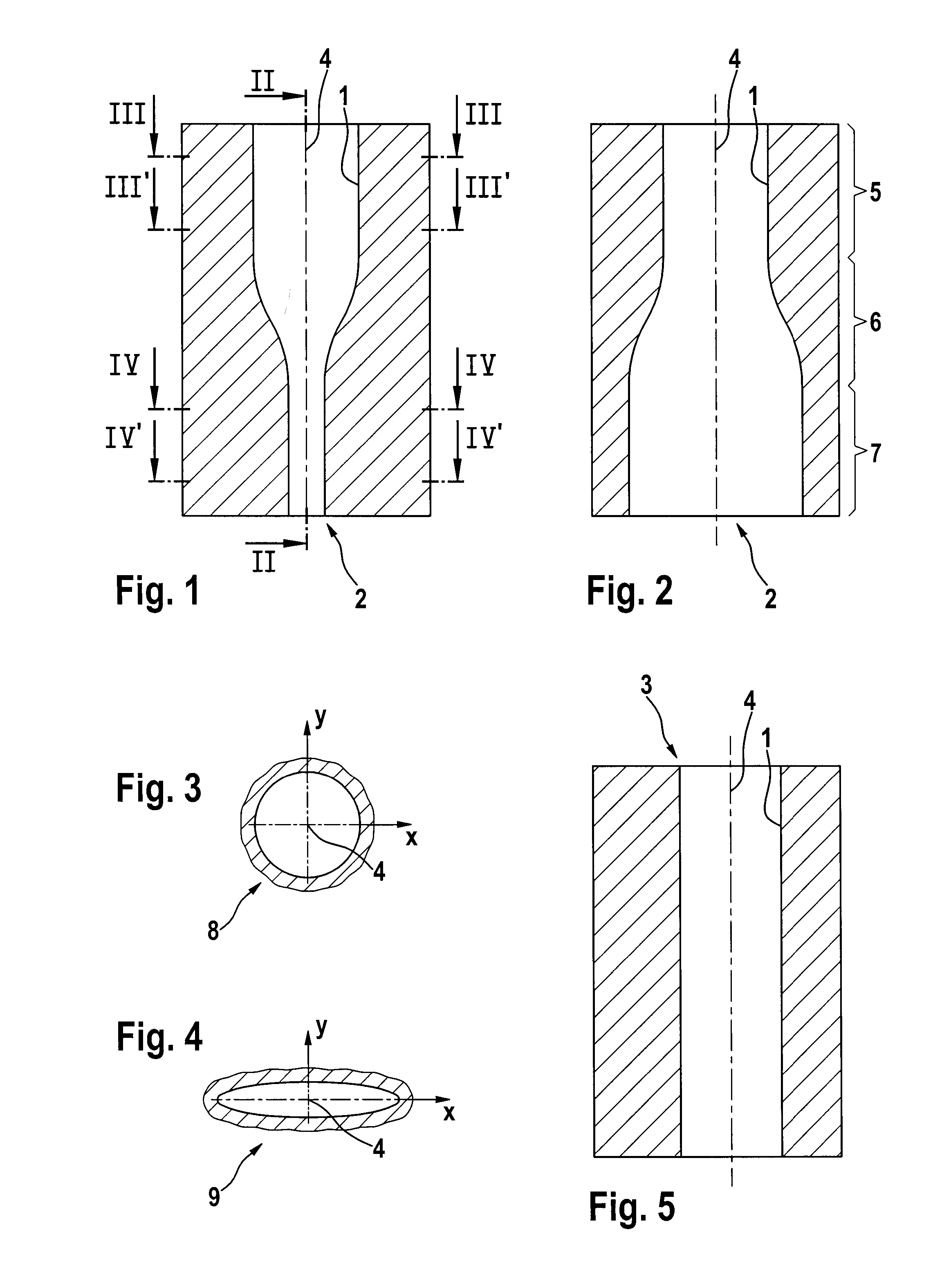
[0018] For the manufacture of a bore 1 with the cylindrical nominal shape 3 illustrated in Fig. 5, which nominal shape results by deformation in the operational state, first the initial shape 2 of the bore 1 illustrated in Figs. 1 and 2 is determined. The initial shape 2 is the shape of the bore 1 before being mounted. The initial shape 2 is substantially cylindrical in its upper area 5 and elliptical in its lower area 7. The illustration of the deviation of the elliptical shape from the cylindrical shape is not true to scale in Figs. 1 and 2 but is shown greatly enlarged. In fact, the deviation is in the range of approximately 8 to 60 m. The central area 6 is a transition area from the cylindrical cross-sectional shape 8 to the elliptical cross-sectional shape 9. The cylindrical cross-sectional shape 8 is illustrated in Fig. 3 and the elliptical cross-sectional shape 9 in Fig. 4.

[0019] For determining the initial shape 2 the deformation of the nominal shape 3 in the operational sta...


PUM


Abstract

Abstract of Disclosure In a method for producing a bore, wherein the bore in an unloaded state has an initial shape and in an operational state has a nominal shape deviating from the initial shape, first a deformation of the bore to a nominal shape present in an operational state is determined. Based on the nominal shape and the deformation determined in the first step, the initial shape is determined. The bore is then transformed by a processing method to the initial shape.

Description

Background of Invention[0001] 1. Field of the Invention.[0002] The invention relates to a method for machining a bore, in particular, the cylinder bore of a reciprocating piston machine, wherein the bore in the unloaded state has an initial shape and in the operational state has a nominal shape which deviates from the initial shape.[0003] 2. Description of the Related Art.[0004] In particular in the case of cylinder bores of reciprocating piston machines such as internal combustion engines or compressors, the goal is to obtain excellent tribological conditions by providing uniform and minimal play between piston and cylinder. Since, as a result of loads caused by stress and temperatures in the operational state, the cylinder bore is deformed, the shape of the bore which is cylindrical in the unloaded state deviates in operation from the cylindrical shape.[0005] In order to provide a cylindrical bore during operation, it is proposed in Japanese patent document 11267960 to clamp the b...

Claims


Application Information

Patent Timeline
IPC IPC(8): B24B33/02B24B33/06B24B33/08
CPCB24B33/02B24B33/088
Inventor KLINK, ULRICHFLORES, GERHARD
Owner MASCHFAB GEHRING
Why Eureka
Try Eureka