Thermal deck

a deck and thermal insulation technology, applied in the field of house insulation, can solve the problems of poor heat transfer characteristics, poor conductors, and less than desirable insulation properties of roof systems, and achieve the effect of improving insulation and heat transfer characteristics

Inactive Publication Date: 2003-07-10
ELLIS BILLY
View PDF0 Cites 54 Cited by
  • Summary
  • Abstract
  • Description
  • Claims
  • Application Information

AI Technical Summary

Benefits of technology

[0009] It is an object of the present invention to provide a radiant barrier material having improved insulation and heat transfer characteristics for a residential or industrial building.
[0010] It is another object of the present invention to provide a radiant barrier system that eliminates static air space which, once heated, would tend to conduct heat through a second wood layer and into the building.
[0011] It is yet another object of the present invention to provide a radiant barrier material that is more efficient and economical to use.

Problems solved by technology

However, such ceiling and roof systems can have less than desirable insulation properties and thus additional insulation is often used.
The problem with such a design is that heat is conducted through the first wood layer to the foil barrier.
Foil is a good conductor but a poor radiator.
Once the air space is heated, it is difficult to cool down and heat is conducted through the second wood layer and into the building.

Method used


Image

  • Thermal deck
  • Thermal deck
  • Thermal deck

Examples


second embodiment

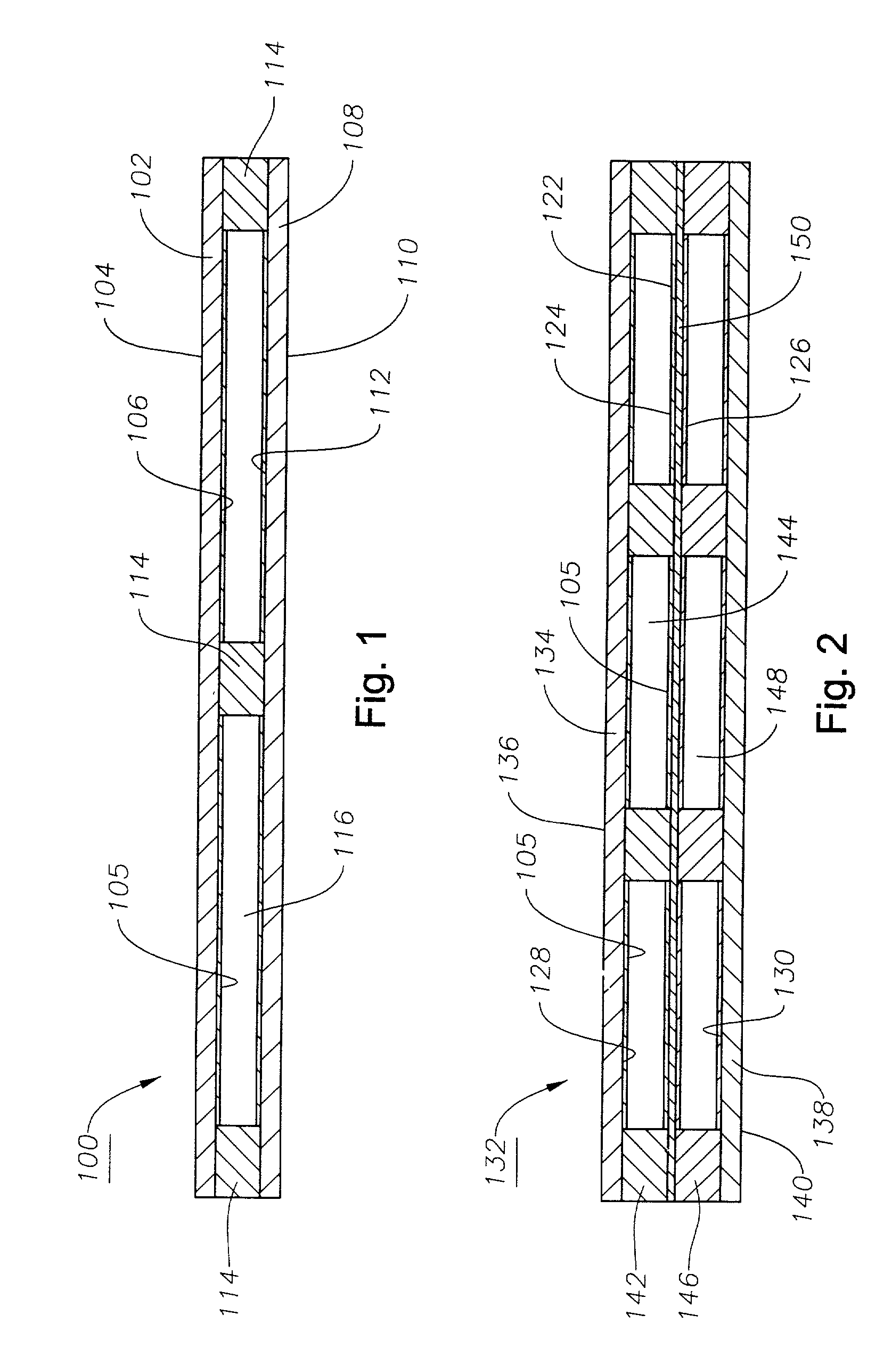
[0027] In a second embodiment shown in FIG. 2, a thermal decking 132 comprises a first panel 134 having an outside surface 136 and an inside surface 128. First panel 134 can be any desired thickness but is preferably about 1 / 2" thick 4' wide and 8' long. A second panel 138 has an outside surface 140 and an inside surface 130 that faces the inside surface 128 of the first panel 134. Inside surfaces 128 and 130 optionally may be covered with foil 105. The second panel 138 can also be of any desired thickness but is preferably about 1 / 4" thick 4' wide and 8' long or alternatively is about 1 / 2" thick 4' wide and 8' long. Positioned between the first panel 134 and the second panel 138 is a radiant barrier 122. The radiant barrier 122 is a panel with a top side 124 and a bottom side 126 such that the top side 124 faces the inside surface 128 of the first panel 134 and the bottom side 126 faces the inside surface 130 of the second panel 138. Top side 124 and bottom side 126 are covered wit...

first embodiment

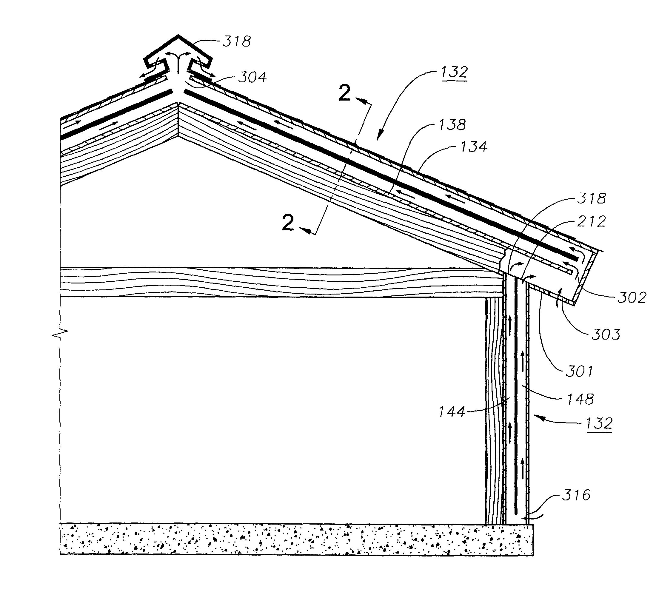
[0034] Referring to FIG. 4, thermal decking 132 could also be installed on conventional roof rafters in much the same manner as the thermal decking 100. If the thermal decking 132 is installed, then the second panel 138 and the radiant barrier 122 on the inlet side 302 may be cut at least 0.5 inch shorter than upper decking 136, leaving a portion of the first panel 134 extending past the second panel 138 and the radiant barrier 122 to create inlet 301. As in the first embodiment, inlet 302 is located in a soffit area 301 that has an opening 303 for air to flow in to inlet 302. A ridge vent 304 may be installed at outlet 304 on the ridge or peak of the roof to enhance air flow.

[0035] As shown in FIG. 4, thermal decking 100, or 132, could also be installed on the wall studs in place of the standard sheathing on side walls. The thermal decking 132 would be orientated such that an inlet 316 is near the base or foundation of the house while the outlet 318 is near the soffit area 202 of t...


PUM


Abstract

A decking assembly is mounted to a building roof or wall to thermally insulate the buildingt. The decking assembly has a first panel with an outside surface and a foil covered inside surface and a second panel having an outside surface and a foil covered inside surface. The foil covered inside surface of the second panel faces the foil covered inside surface of the first panel. At least one spacer is positioned between the panel so as to create an air space defined by the foil covered inside surfaces. The air space has an open inlet and outlet to create a continuous conduit for the flow of air from an entrance side to an exhaust side. The air space can be divided into two separate compartments by a barrier panel that has foil on opposite sides.

Description

BACKGROUND OF THE INVENTION[0001] 1. Technical Field[0002] The present invention relates generally to insulating a house and particularly to insulating a house using decking and still more particularly to insulating the roof of a house using insulated decking.[0003] 2. Description of the Related Art[0004] The roof system of a conventional residential building includes uniformly spaced joists spanning the length between pairs of parallel support beams, the joists forming the ceiling. Wallboard and 2.times.6 boards may be placed on top of the uniformly spaced joists. Metal or wood trusses are then erected above the joists to form the framing for the roof. Exterior plywood sheathing is applied on top of the trusses and an exterior covering, such as a roofing felt and either asphalt, metal roofing or wood shingles, is then secured to the exterior surface of the sheathing. Often, soffits, or ventilated panels are installed to allow air to circulate freely, helping prevent problems with e...

Claims


Application Information

Patent Timeline
Patent Type & Authority Applications(United States)
IPC IPC(8): E04B7/20E04D13/17
CPCE04D13/17E04B7/20
Inventor ELLIS, BILLY
Owner ELLIS BILLY
Why Eureka
Try Eureka