Small-sized hydroelectric power generating apparatus

a hydroelectric power generation and small-scale technology, applied in the direction of electric generator control, renewable energy generation, greenhouse gas reduction, etc., can solve the problems of ineffective electric power generation, water wheel rotation not smooth, water wheel rotation not at all, etc., to achieve the effect of effective power generation and small loss of effective magnetic flux

Inactive Publication Date: 2003-07-10
YUMITA YUKINOBU +1
View PDF1 Cites 14 Cited by
  • Summary
  • Abstract
  • Description
  • Claims
  • Application Information

AI Technical Summary

Benefits of technology

0010] In view of the above problem, a first object of the invention is to provide a small-sized hydroelectric power generating apparatus constructed so that in order to effectively generate electric power with a small amount of flowing water, detent torque between the a rotor magnet and a pole tooth is kept low, and the loss of magnetic fluxes effective to power generation is small.

Problems solved by technology

Therefore, such a problem is produced that the water wheel does not rotate smoothly, or the water wheel does not rotate at all if the amount of the flowing water is a little.
Accordingly, if the gap between them is made wider than it needs, the electric power cannot be generated effectively.
From this reason, in this type of small-sized hydroelectric power generating apparatus, such a proposition that power generation is performed efficiently with a smaller amount of flowing water cannot be solved.
However, in case that the number of the ejection holes is three or more, and the ejection hole is not opposed to the central axis but orthogonally opposed to the vane, machining is very complicated and expensive.
Therefore, the rotational efficiency of the water wheel was low and the power generating efficiency was also low.

Method used


Image

  • Small-sized hydroelectric power generating apparatus
  • Small-sized hydroelectric power generating apparatus
  • Small-sized hydroelectric power generating apparatus

Examples


Embodiment Construction

[0037] A small-sized hydroelectric power generating apparatus according to a mode for carrying out the invention will be described with reference to drawings.

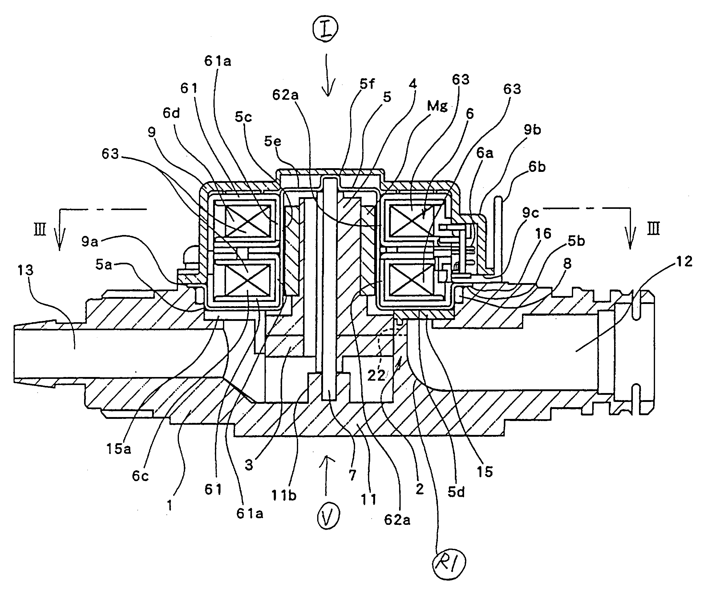
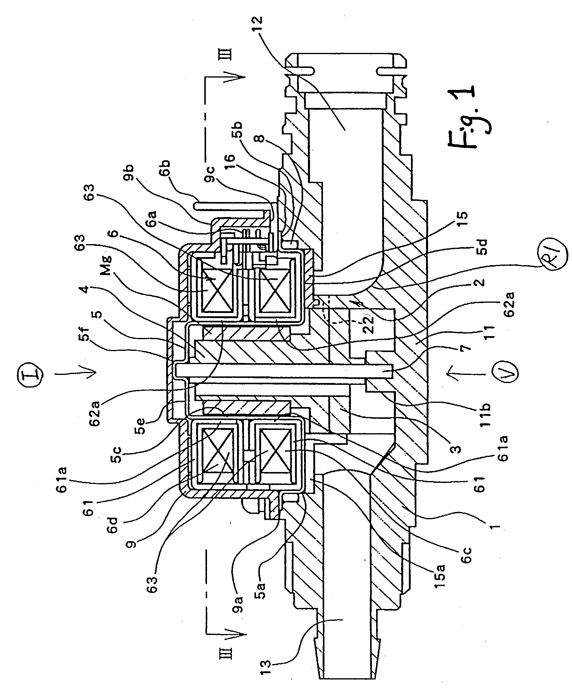
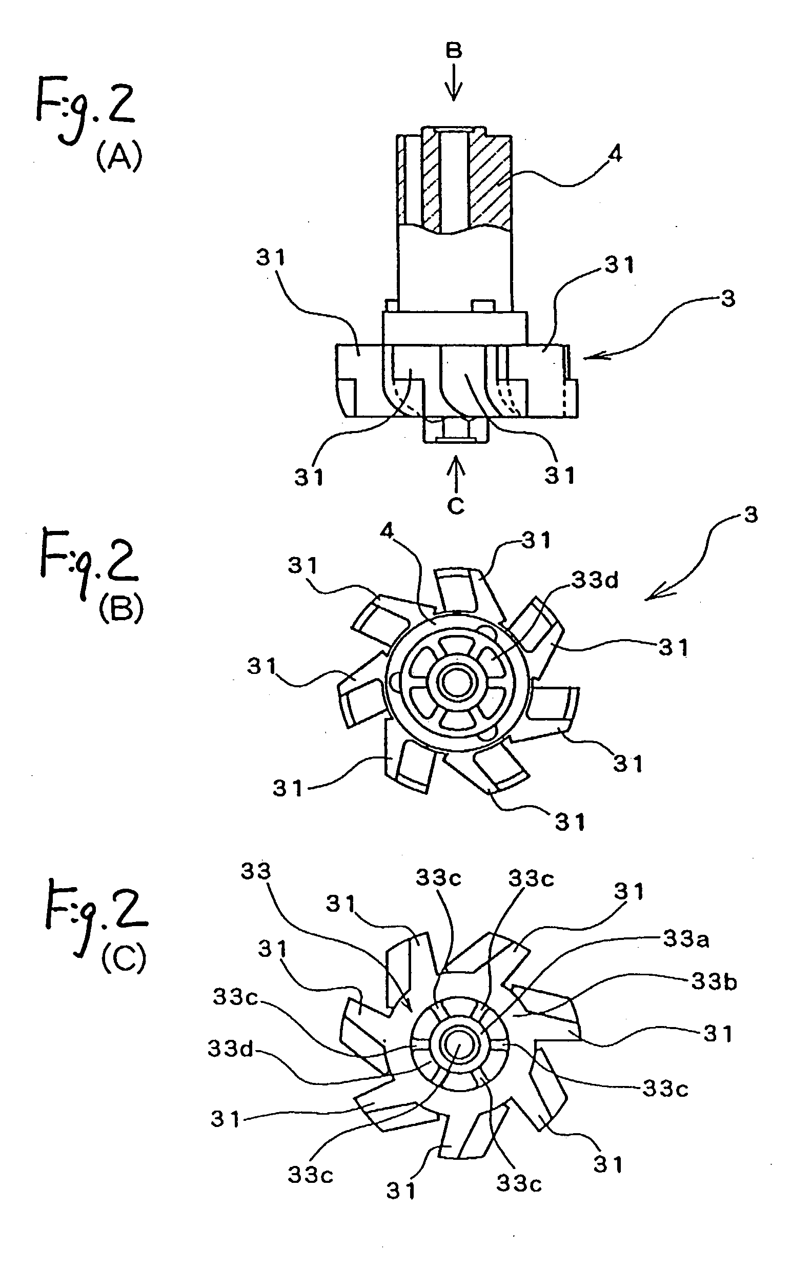
[0038] As shown in FIG. 1, the small-sized hydroelectric power generating apparatus according to the mode for carrying out the invention includes a body case 1 having an inlet 12 of a fluid passage and an outlet 13, a water spouting portion 2 that is provided in the body case 1 and functions as a part of the fluid passage, a water wheel 3 that is arranged inside of the water spouting portion 2 and rotates with passing of the predetermined amount of fluid, a rotator 4 that is coupled to the water wheel 3 and rotates together with the water wheel 3, a stainless cap-shaped case 5 that is arranged outside of the rotator 4 and fitted in the body case 1 thereby to form an inner space in cooperation with the body case 1, and a stator portion 6 arranged outside this cap-shaped case 5.

[0039] The body case 1 includes a main body 11, and ...


PUM


Abstract

A small-sized hydroelectric power generating apparatus includes a body case having a fluid passage, a water wheel provided at the above fluid passage and rotating with passing of the fluid having the predetermined flowing amount, a rotator coupled to this water wheel, and rotating with the water wheel, the rotator serving as a rotor portion arranged opposed to a stator portion, the rotor portion being relatively rotated in relation to the stator portion by passing the fluid to generate electric power, the stator portion having comb-shaped pole teeth which are arranged in the circumferential direction at regular intervals so as to be opposed to the peripheral surface of a rotor magnet of the above rotor portion, and a circumferential gap between the adjacent pole teeth is set to 1.5 times or less the size of a radial gap between each pole tooth and the rotor magnet.

Description

BACKGROUND OF INVENTION[0001] 1. Field of Invention[0002] The present invention relates to a small-sized hydroelectric power generating apparatus using water power generated by flow of water passing through a faucet.[0003] 2. Related Art[0004] Conventional, an automatic water faucet apparatus is known well, in which by detecting by a sensor that a user holds out his hand beneath a faucet, water flows from the faucet. Further, recently, an apparatus is also proposed, in which a small-sized power generating apparatus is provided at a fluid passage of such the automatic water faucet apparatus, and the consumption power of a circuit of the afore-mentioned sensor is supplied by storing the electric power obtained by this small-sized power generating apparatus (refer to Unexamined Japanese Utility Model Publication Hei. 2-65775).[0005] The constitution of the afore-mentioned small-sized hydroelectric power generating apparatus will be briefly described below. A water wheel is provided at ...

Claims


Application Information

Patent Timeline
Patent Type & Authority Applications(United States)
IPC IPC(8): F03B3/00H02K7/18H02K29/00
CPCF03B3/00Y02E10/223H02K7/1823F05B2240/90Y02E10/20
Inventor YUMITA, YUKINOBUTSURUTA, TOSHIFUMI
Owner YUMITA YUKINOBU
Why Eureka
Try Eureka