Projection lens unit of projection television

a technology of projection television and projection lens, which is applied in the field of projection devices, can solve the problems that front-type liquid crystal projection devices are not suitable for wall-type projection devices in houses

Inactive Publication Date: 2003-07-10
SAMSUNG ELECTRONICS CO LTD
View PDF17 Cites 13 Cited by
  • Summary
  • Abstract
  • Description
  • Claims
  • Application Information

AI Technical Summary

Benefits of technology

[0015] In a further exemplary embodiment of the present invention, the second coupling device is formed of a material that has a predetermined thermal expansion coefficient. In addition, the third single body is attached to the inner surface of the second coupling portion.
[0016] The reflection mirror may be installed on the inner surface of the third single body or, though a separate structure, on the outer surface of the third single body.
[0017] In the projection lens unit according to exemplary embodiments of the present invention, lens groups, which focus and project an image generated by an image generating source to a screen, are installed in single bodies, while a reflection mirror is installed in the same single body. Consequently, the lens groups and the reflection mirror are conveniently arranged. In addition, the single bodies are coupled to each other and are able to rotate so as to adjust the focus of the projection lens unit. Thereby, the extent of a defocused state of the projection lens unit is minimized.

Problems solved by technology

In particular, the depths D1 and D2 of the set cases 1 and 2 of the front-type liquid crystal projection devices are great, so that the front-type liquid crystal projection devices are not suitable as wall-type projection devices in a house.
However, problems related to the arrangement of the first and second lens groups L1 and L2 and the reflection mirror M remain so that the optical axis may alter or the defocused state of the arrangement may be increased.

Method used


Image

  • Projection lens unit of projection television
  • Projection lens unit of projection television
  • Projection lens unit of projection television

Examples


Embodiment Construction

[0033] A projection lens unit of a projection television (TV) according to the present invention will be described in detail with reference to the attached drawings. In the drawings, the thickness of the layers and regions are exaggerated for clarity.

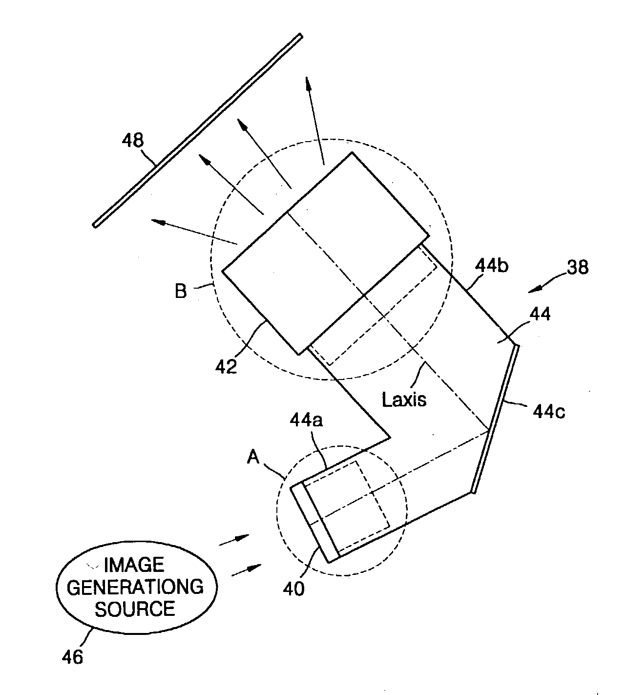
[0034] Referring to FIG. 5, a projection lens unit 38 according to an embodiment of the present invention is formed of first through third single bodies 40, 42, and 44. The first single body 40 focuses a beam, namely an image having predetermined image information generated by an image generating source 46, i.e., a liquid crystal device (LCD) or a cathode ray tube (CRT), to a reflection portion 44c arranged in the third single body 44. The first single body 40 includes a first lens group (not shown) having positive power. It is preferable that the first lens group is formed of at least one convex lens, at least one concave lens, and an aspheric lens for adjusting an optical axis so as to solve or relieve an optical aberration problem. T...


PUM


Abstract

A projection lens unit of a projection television (TV) includes a first lens group for focusing an image incident from an image generating source, a reflection mirror for reflecting the image projected from the first lens group, and a second lens group having the same optical axis as the optical axis of the first lens group for magnifying and projecting the image reflected from the reflection mirror to a screen. The first and second lens groups are installed in first and second single bodies, which are coupled to a third single body having the reflection mirror to reflect the image incident from the first single body to the second single body. By this arrangement, the focus of the projection lens unit is easily adjusted and the lens groups are conveniently coupled to each other. In addition, a defocused state of the projection lens unit can be easily minimized.

Description

[0001] 1. Field of the Invention[0002] The present invention relates to a projection device for projecting an image generated by an image generating source to a frontal screen so as to display the image on the screen, and more particularly, to a projection lens unit for magnifying and projecting an image to a screen.[0003] 2. Description of the Related Art[0004] Image projection devices, such as projection televisions (TV) or video projectors, magnify and project images to a screen through a projection lens unit in order to display the images. Therein, the images are generated by an image generating device, such as a liquid crystal device (LCD) or a small-sized cathode ray tube (CRT). As widely known, image projection devices are divided into front-type image projection devices and rear-type image projection devices according to the method used to magnify and project the images generated by the image generating device.[0005] FIGS. 1 and 2 illustrate conventional front-type liquid cr...

Claims


Application Information

Patent Timeline
Patent Type & Authority Applications(United States)
IPC IPC(8): G02B7/02G02B7/04G02B13/16G02B17/08G03B21/00G03B21/14H04N5/64H04N5/74
CPCG02B7/04H04N5/7408G02B13/16H04N5/74
Inventor PARK, SUNG-MINNHO, JEONG-HO
Owner SAMSUNG ELECTRONICS CO LTD
Why Eureka
Try Eureka