Valve for use in high pressure gas containers

Inactive Publication Date: 2003-07-17
HAMAI INDS
View PDF20 Cites 12 Cited by
  • Summary
  • Abstract
  • Description
  • Claims
  • Application Information

AI Technical Summary

Problems solved by technology

Accidents due to ignition in high pressure vessels sometime occur when oxide gas is removed from the gas vessels.
However, when using oxygen bombs for medical use, for example, it is necessary to supply oxygen to patients in an emergency, so that the operator cannot pay attention to the caution that the operation valve should

Method used


Image

  • Valve for use in high pressure gas containers
  • Valve for use in high pressure gas containers
  • Valve for use in high pressure gas containers

Examples


Embodiment Construction

[0046] The on-off valve for use in high pressure oxygen vessels according to the preferred embodiments of the present invention will be explained, referring to the attached drawings.

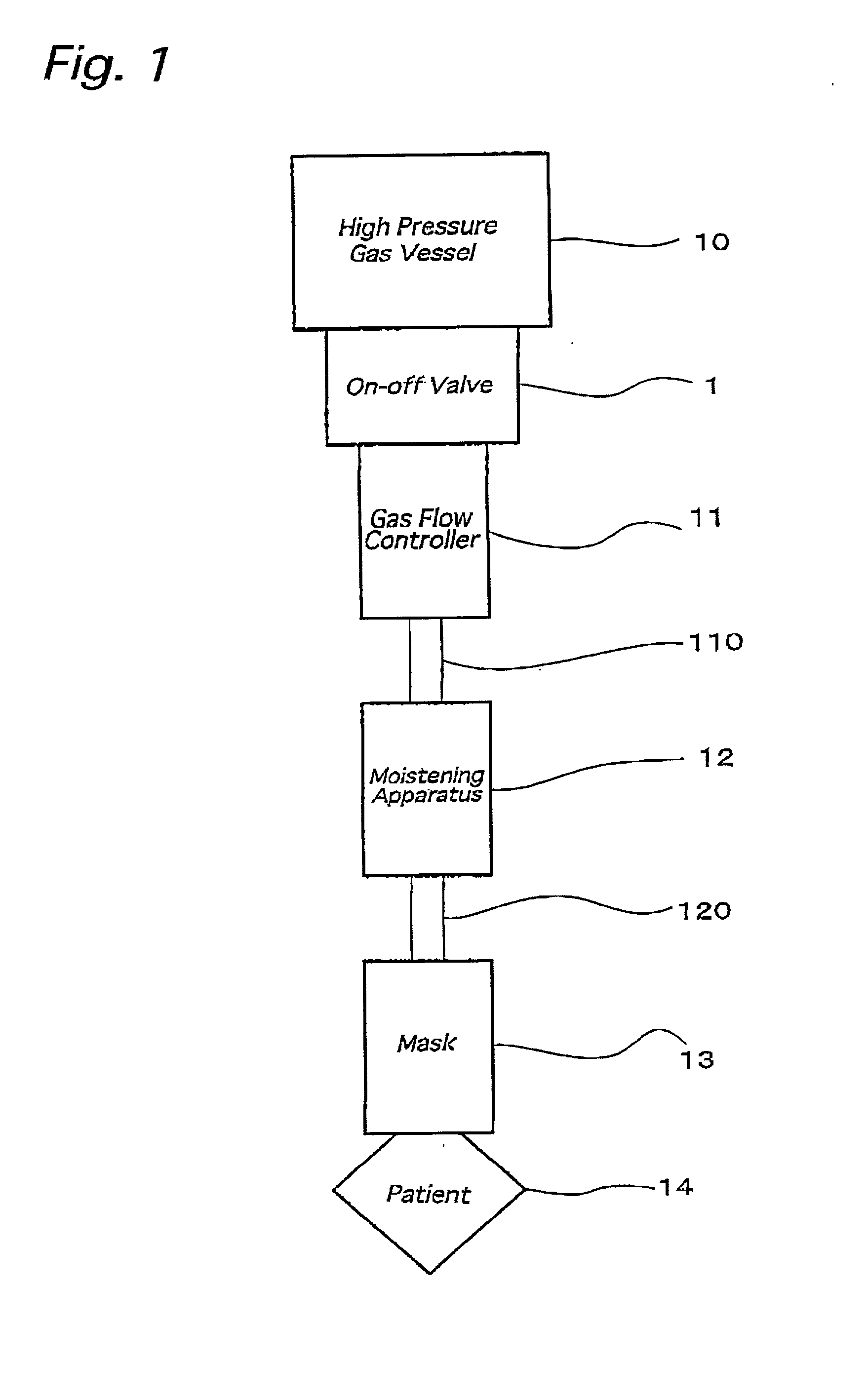
[0047] FIG. 1 is a block diagram showing an oxygen inhalation system for medical use where an on-off valve 1 for use in high pressure oxygen vessels according to the invention is used.

[0048] A gas high pressure container 10 is constituted of a compact type bomb in order make it portable. For instance the bomb has a capacity of 1.about.10 liter and an outer diameter of 100-150 mm. The vessel 10 has a connecting member, which is connected to the inside of the vessel 10, to which an on-off valve 1 for use in high pressure oxygen gas vessel is connected, so as to interrupt or open the exhaust of the oxygen gas from the vessel 10. The gas inlet of a gas flow controller 11 is connected to the oxygen gas outlet of the valve 1. To the outlet of the gas flow controller 11, a connecting hole at the upper stream si...


PUM


Abstract

An on-off valve mounted in a high pressurized gas container, which has a holding portion for holding a flow amount controlling member in a path formed in an upper stream side of the body of the valve, and in which a flow amount controlling member is movably held. In the flow amount controlling member, an orifice is formed. When the valve moves into an opening position, a high pressurized oxygen gas is flowed into a valve chamber by gas pressure, the flow amount controlling member moves and closes the path. At this time, the gas flow amount is restricted by the orifice, so that the pressurizing speed of the gas pressure at the down stream side of the orifice becomes slow and then heat generation due to the adiabatic compression is reduced.

Description

[0001] 1) Field of the Invention[0002] The present invention relates to an on-off valve for use in high pressure gas vessels, More particularly, This invention relates to an on-off valve where the flow amount of gas is restricted when the valve is made off.[0003] 2) Prior Art[0004] Accidents due to ignition in high pressure vessels sometime occur when oxide gas is removed from the gas vessels. The following are considered causes of such accidents: (1) An Oxide per se is an essential for ignition; (2) when a highly pressures gas flows into an airtightened space of an apparatus, which is connected to the outlet side of the operation valve of a high pressure vessel heat is instantaneously generated due to adiabatic compression; and (3) the sealing member or lubricant of the valve, or dust in the valve acts as an ignition material.[0005] In order to prevent such accidents, cautions are known such that when opening the valve of such a high pressure vessels the operating handle should be ...

Claims


Application Information

Patent Timeline
IPC IPC(8): A61M16/20A62B9/02F16K1/30F16K47/10
CPCA61M16/20A62B9/02F16K47/10F16K1/306F16K1/307F16K1/305A61M16/209
Inventor KIKUCHI, TOSHIAKI
Owner HAMAI INDS
Why Eureka
Try Eureka