DC inductive shorted patch antenna

a technology of inductive shorting and patch antenna, which is applied in the direction of antennas, antenna details, antenna earthings, etc., can solve the problems of reducing fabrication costs, not meeting the present design goals of the antenna, and having very little room in the product of wireless devices such as pda's and laptops

Inactive Publication Date: 2003-07-24
OAE TECH INC
View PDF10 Cites 49 Cited by
  • Summary
  • Abstract
  • Description
  • Claims
  • Application Information

AI Technical Summary

Benefits of technology

0011] By way of introduction only, the present embodiments provide a direct current (DC) inductive shorted patch antenna. In another embodiment, an antenna including a direct current inductive (DCL) frequ

Problems solved by technology

Manufacturers of wireless devices such as handsets, PDA's and laptops have very little room in their products given these extreme size and cost pressures.
Such wireless devices typically pack a substantial amount of circuitry in a very small package.
To date, however, none of these antennas satisfy the present design goals, which specify efficient, compact, low profile antennas whose height is at most .lam

Method used


Image

  • DC inductive shorted patch antenna
  • DC inductive shorted patch antenna
  • DC inductive shorted patch antenna

Examples


Embodiment Construction

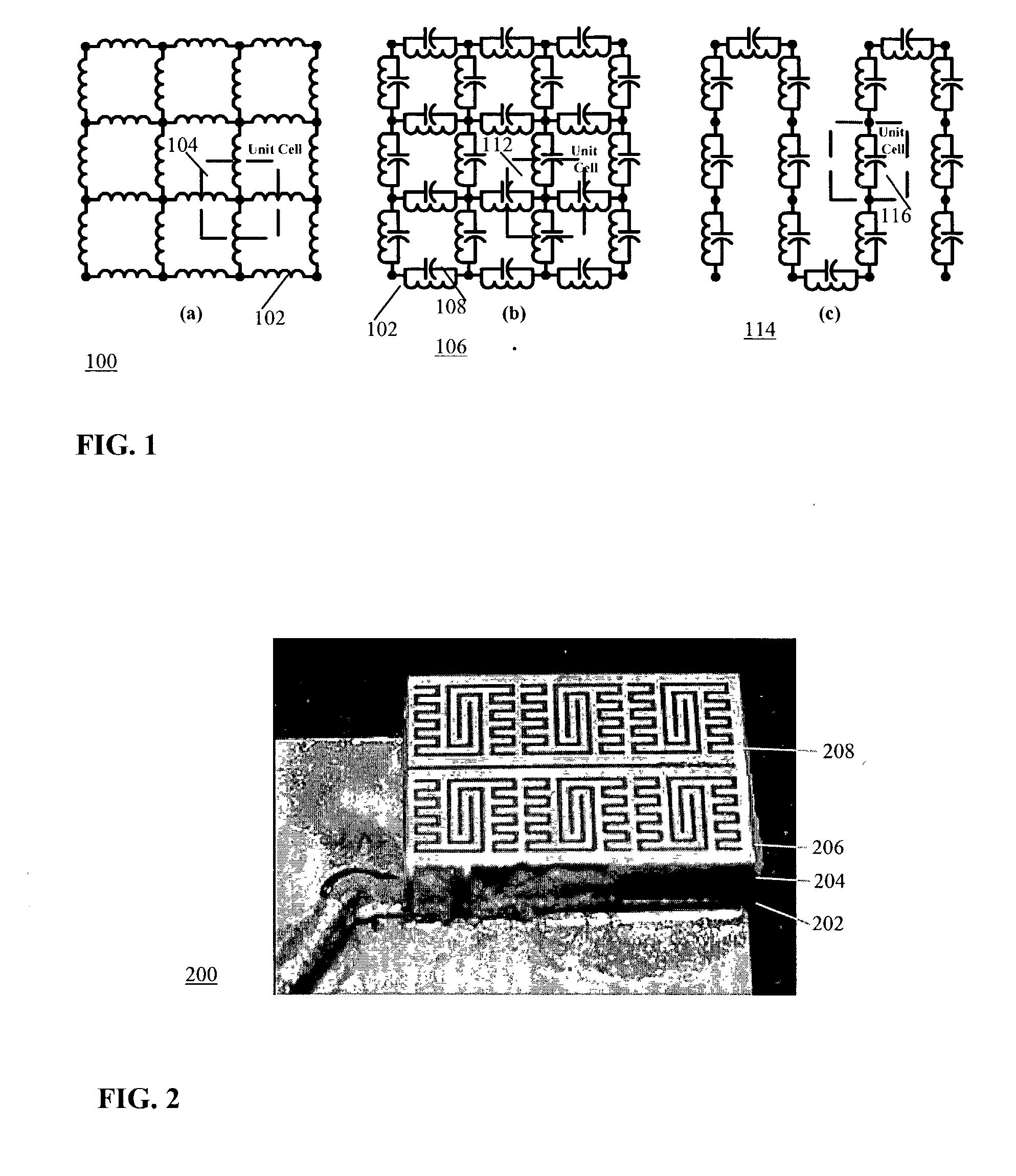
[0028] Referring now to the drawing, FIG. 1 shows equivalent circuits for direct current inductive frequency selective surface (DCL FSS) structures. A DC inductive (DCL) frequency selective surface (FSS) is a periodic surface of conductors, which form a lattice or grid 100 of inductors as shown in FIG. 1(a). An example is a coplanar grid of wires intersecting at right angles. Each wire in the grid 100 may be modeled as an inductor 102 having a characteristic inductance. Further, a unit cell 104 may be defined so that the model may be dimensioned to have any suitable size.

[0029] A more detailed model 106 is shown in FIG. 1(b). In the model 106, capacitors 108 are added in parallel with the inductors 102 to model conditions in a real embodiment of a DCL FSS. There will always be a small amount of parasitic capacitance between the wires, which acts to shunt the inductance. Again, a unit cell 112 models the contribution of each wire to the overall DCL FSS. A DCL FSS can be designed with...


PUM


Abstract

A direct current (DC) inductive shorted patch antenna includes a direct current inductive (DCL) frequency selective surface (FSS) forming the radiating element, a ground plane, a feed, and a radio frequency (RF) short to the ground plane positioned between the feed and the radiating element.

Description

[0001] This application claims priority of U.S. Provisional Patent application serial No. 60 / 354,003 filed Jan. 23, 2002. This application is related to U.S. Provisional Patent Application serial No. 60 / 352,113 filed Jan. 23, 2002 and Provisional Patent application serial No. 60 / 354,697 filed Feb. 4, 2002 in the names of Greg S. Mendolia, John Dutton and William E. McKinzie III and entitled "MINIATURIZED REVERSE-FED PLANAR INVERTED-F ANTENNA, which applications are hereby incorporated herein by reference in their entirety. This application is related to U.S. Provisional Patent Application serial No. 60 / 310,655 filed Aug. 6, 2001 in the names of William E. McKinzie III, Greg S. Mendolia and Rodolfo E. Diaz and entitled "LOW FREQUENCY ENHANCED FREQUENCY SELECTIVE SURFACE TECHNOLOGY AND APPLICATIONS," which application is incorporated herein by reference in its entirety.[0002] The present invention relates generally to antennas. More particularly, the present invention relates to a rev...

Claims


Application Information

Patent Timeline
IPC IPC(8): H01Q5/00H01Q9/04H01Q15/00
CPCH01Q15/0013H01Q9/0421
Inventor MCKINZIE, WILLIAM E. IIIMENDOLIA, GREG S.DUTTON, JOHN
Owner OAE TECH INC
Why Eureka
Try Eureka