Segmented distribution headlight system, method, and apparatus

a distribution headlight and segmented technology, applied in the direction of point-like light sources, transportation and packaging, lighting and heating apparatus, etc., can solve the problems of affecting the visibility of both drivers, affecting the ability of other drivers to see, or glare on either side, so as to maximize the ability of all drivers to see and maximize the amount of light

Inactive Publication Date: 2003-07-24
ALDEN RAY M
View PDF3 Cites 71 Cited by
  • Summary
  • Abstract
  • Description
  • Claims
  • Application Information

AI Technical Summary

Benefits of technology

0006] The present invention is a system for automatically controlling the distribution of a headlight in response to environmental conditions wherein, a means for sensing the locations of other vehicles is provided, said means dividing the exterior space into sectors and determining if an automobile is present in each respective sector. Additionally a headlight is provided which comprises a means for illuminating each said respective sector independently. Moreover automated control of the headlight intensity and or direction is provided at the sector level. The result is that the present headlight can stay on high beam in all sectors which do not contain a motor vehicle and concurrently go on low beam only in those sectors which do contain a motor vehicle. This maximizes the ability of all drivers to see at all times.
0007] Thus the present invention offers a significant advancement in vehicular headlight systems.
0008] Accordingly, several objects and advantages of the present invention are apparent. It is an object of the present invention to maximize the amount of light that the driver can use without inhibiting the ability of other drivers to see. It is an advantage of the present invention to provide

Problems solved by technology

Heretofore a tradeoff has existed between a driver benefiting from a high beam to see further ahead and that high beam costing the ability of other drivers' visibility (blinding them with glare).
Often, this tradeoff creates a problem where either one, or the other, or both drivers' visibility is inhibited b

Method used


Image

  • Segmented distribution headlight system, method, and apparatus
  • Segmented distribution headlight system, method, and apparatus
  • Segmented distribution headlight system, method, and apparatus

Examples


first embodiment

[0014] FIG. 5 illustrates the segmented headlight means and controlling switch array in a

second embodiment

[0015] FIG. 6 illustrates headlight distribution area segmenting means of a

[0016] FIG. 7 is identical to FIG. 6 except that the alternate segmented electro-chromatic element 127a is incorporated into the optic (whereas they were separate components in FIG. 6).

[0017] FIG. 8 the element of an individual electro-optic cell in a first state.

[0018] FIG. 9 is an electro-optic material in a second state of alignment.

third embodiment

[0019] FIG. 10 depicts a segmented headlight with individually controlled sectors of distribution of the

[0020] FIG. 11 illustrates the art of the present invention being used to concentrate light to look around corners in response to road conditions.

[0021] FIG. 12 illustrates the art of the present invention being used to concentrate light to look up a hill in response to road conditions.

[0022] FIG. 13 illustrates the art of the present invention being used to concentrate light to look down a hill in response to road conditions.

[0023] FIG. 14 illustrates the segmented distribution light of the present invention integrated with the position of a steering wheel.

[0024] FIG. 15 is the steering wheel of FIG. 14 in a new position.

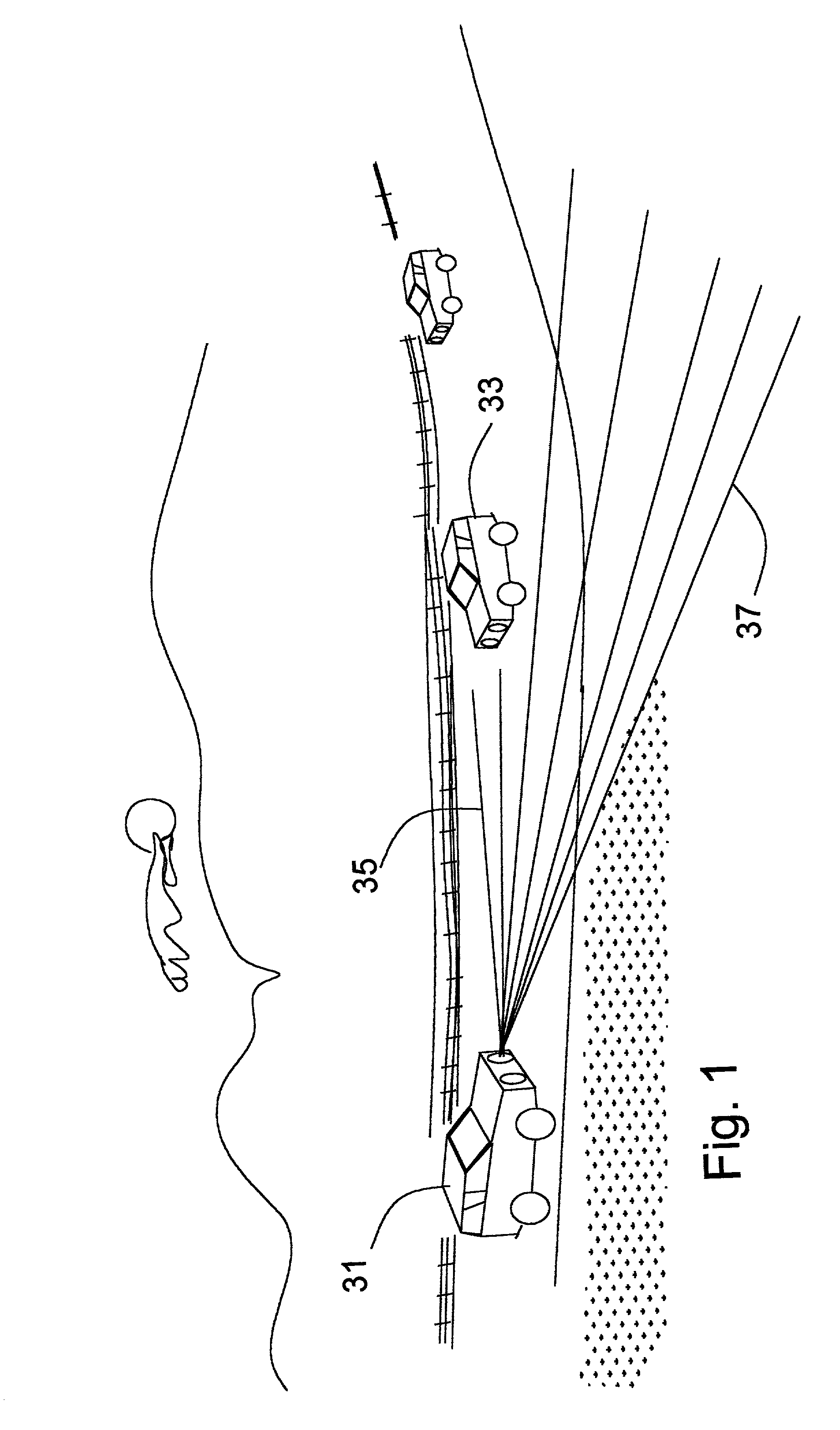
[0025] FIG. 1 depicts a vehicle employing an automatic segmented illumination means of the present invention. A first vehicle 31 emits a low beam illumination 35 in a first headlight distribution sector while concurrently emitting a high beam,illumination 37 in a...


PUM


Abstract

The invention described herein represents a significant improvement in the art of headlights for vehicles. A first element is provided as a means for sensing the presence and location of other motor vehicles, said means for sensing connected to processing and light controlling circuitry such that the electrical current supplied to each element in an array of elements is individually controlled. The result is a headlight system which produces high beams in areas where no vehicle is present and concurrently produces low beams in areas where vehicles are present. In a first embodiment, individual light elements in array are individually controlled with regard to intensity to provide dim beam areas and high beam areas concurrently. In a second embodiment, individual electro-chromatic elements in array are individually controlled so as to provide a means to create dim beam areas and high beam areas concurrently. In a third embodiment, variable refractive segments in array are individually controlled to redirect beam portions such that high beam and dim beam areas are created concurrently. All embodiments maximize the areas receiving high beams for the benefit of the equipped vehicle driver while concurrently all areas with other drivers present receive low beams so as to minimize the glare for to betterment of other drivers.

Description

BACKGROUND FIELD OF INVENTION[0001] Over the past one hundred years, electric lighting has been implemented using many well know techniques to provide illumination in many applications. Well known electrical illumination techniques include incandescent, gas, and LED to name a few. In more recent decades, the prior art has incorporated sensors to control the on or off condition of a light source to provide illumination only when desired and to discontinue (or alternately dim) illumination when desired. Specifically, implementation of variable distribution vehicle headlights has been described in the prior art wherein a first vehicle includes a means to sense the presence or intensity of oncoming vehicle headlights of a second vehicle so as to automate the process of switching headlights of the first vehicle between a state of high beam and low beam.[0002] The present invention provides a significant advancement in variable distribution headlights by providing a means to automatically...

Claims


Application Information

Patent Timeline
IPC IPC(8): B60Q1/08B60Q1/12B60Q1/14B60Q1/18
CPCB60Q1/085B60Q1/12B60Q1/1423B60Q1/18B60Q2300/054F21S48/1747B60Q2300/122B60Q2300/322B60Q2300/324B60Q2300/42F21S48/1159B60Q2300/056F21S41/148F21S41/151F21S41/645F21S41/663
Inventor ALDEN, RAY M.
Owner ALDEN RAY M
Why Eureka
Try Eureka