
Golf club head with adjustable center of gravity

a golf club and center of gravity technology, applied in the field of golf club heads, can solve the problems of not optimizing weight adjustment, achieve the effect of maximizing aesthetic appearance, facilitating movement and fixing weights, and preserving the function of movable weights

Active Publication Date: 2017-07-04
TOPGOLF CALLAWAY BRANDS CORP
View PDF14 Cites 47 Cited by
  • Summary
  • Abstract
  • Description
  • Claims
  • Application Information

AI Technical Summary

Benefits of technology

[0007]The present invention allows consumers to easily move and fix a weight at any location within several channels disposed in a golf club head in such a way to maximize aesthetic appearances while preserving the function of the movable weight. The objective of this invention is to provide an adjustable weight with minimal or no effect on appearance at address while maximizing the ability of the weight to adjust center of gravity location. Additional goals include minimizing the fixed component of the structure dedicated to the weighting system and also minimizing any potential effect on impact sound. Yet another object of the present invention is an adjustable weighting feature for lateral or vertical center of gravity control which is placed to maximize effectiveness and may be entirely concealed from view at address.

Problems solved by technology

The prior art includes several different solutions for adjustable weighting, but these solutions do not optimize weight adjustment.

Method used


Image

  • Golf club head with adjustable center of gravity
  • Golf club head with adjustable center of gravity
  • Golf club head with adjustable center of gravity

Examples


first embodiment

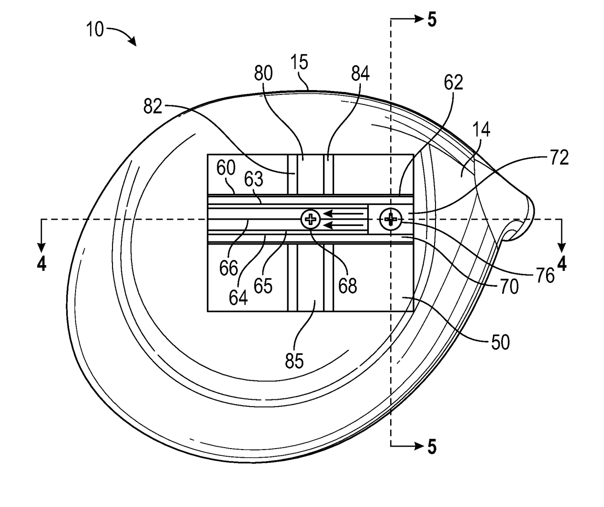
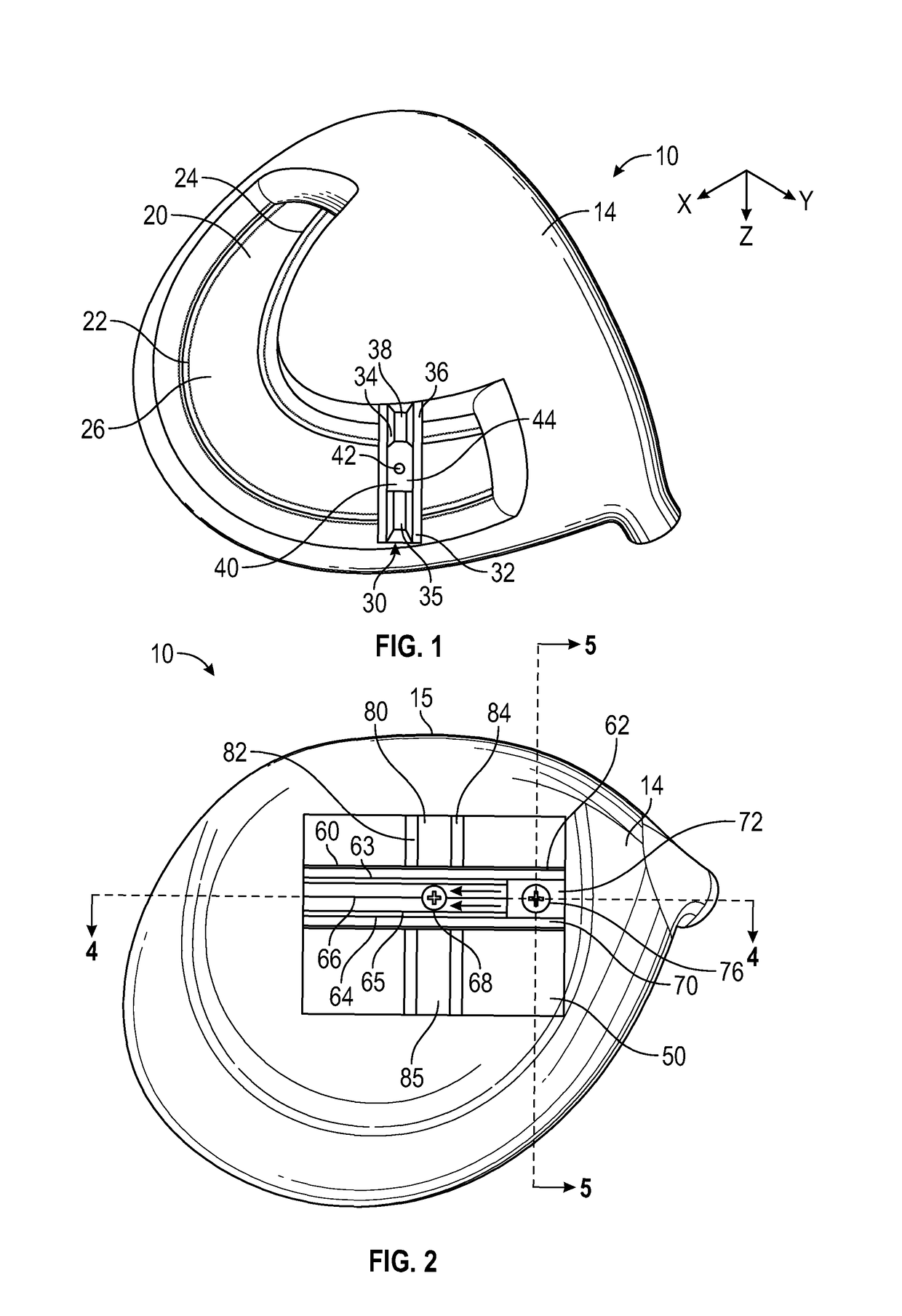
[0027]the present invention is shown in FIG. 1. The golf club head 10 comprises a channel 20 disposed within the sole 14 of the golf club head, though in alternative embodiments the channel 20 may be disposed in a ribbon or skirt portion or in the crown 12 of the golf club head 10. The channel 20 extends from a heel side 16 of the club head proximate a hosel 11 to a toe side 18 of the golf club head 10 along the rear edge of the sole 14, and has a pair of rails 22, 24 extending upwards from the floor 26 of the channel. A slidable, two-piece cartridge 30 is disposed within the channel 20. The cartridge 30 includes an upper portion 32 with a slot 35 sized to receive a slidable weight 40 and a pair of rails 34, 36 extending from a floor 38 of the slot 35, a nutplate (not shown), and a bolt connecting the upper portion 32 to the nutplate. The upper portion 32 and the nutplate are disposed on either sides of the rails 22, 24, and grip the rails 22, 24 between them when the bolt is tighte...

third embodiment

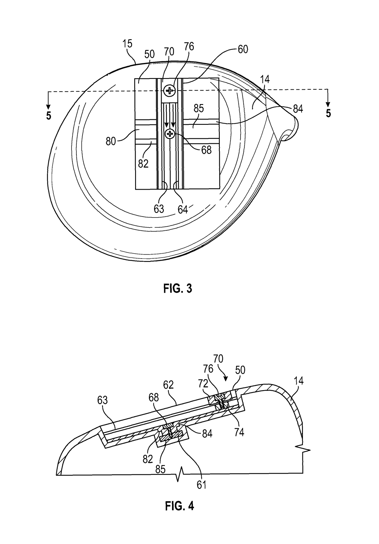
[0030]A fourth, preferred embodiment is shown in FIGS. 6-11. In this embodiment, the golf club head 10 comprises all of the same features as the third embodiment, except that the channel 100 is further recessed into the floor 55 of the rectangular recessed area 50 and comprises a pair of opposing vertical sidewalls 102, 104 from which a pair of rails 103, 105 extend parallel to the floor 106 of the channel 100. The channel 100 is sized to receive the base portion 115 of the elongated weight receptacle 110, which fits between the floor 106 and the rails 103, 105 as shown in FIG. 8. The base portion 115 has a threaded through-bore 116 sized to receive the threaded portion of a bolt 68, and the threaded through-bore 116 aligns with a through bore 113 in a recessed, bolt-receiving portion 114 of the upper portion 112 of the elongated weight receptacle 110. When the bolt 68 is tightened, the base portion 115 and the upper portion 112 clamp onto the rails 103, 105. This configuration allo...


PUM


Abstract

A golf club head comprising features for adjusting the location of the center of gravity along all three axes is disclosed herein. In particular, the head comprises a body with a channel in its sole, at least one slidable receptacle sized to engage the channel, and a slidable weight. The channel preferably comprises a first floor and a pair of rails, while the slidable receptacle comprises a first base portion, a first bolt, and a first upper portion with a slot having a second floor and another pair of rails. The first upper and base portions grip the channel's rails when the first bolt is tightened. Similarly, the slidable weight comprises a second upper portion, a second base portion, and a second bolt, and the second upper and base portions grip the slot's rails when the second bolt is tightened.

Description

CROSS REFERENCES TO RELATED APPLICATIONS[0001]The present application claims priority to U.S. Provisional Patent Application No. 62 / 241,360, filed on Oct. 14, 2015, and is a continuation-in-part of U.S. patent application Ser. No. 14 / 932,171, filed on Nov. 4, 2015, and issued on Apr. 25, 2017 as U.S. Pat. No. 9,630,069, which is a continuation of U.S. patent application Ser. No. 14 / 163,946, filed on Jan. 24, 2014, and issued on Dec. 15, 2015, as U.S. Pat. No. 9,211,453, which claims priority to U.S. Provisional Patent Application No. 61 / 893,728, filed on Oct. 21, 2013, the disclosure of each of which is hereby incorporated by reference in its entirety herein.STATEMENT REGARDING FEDERALLY SPONSORED RESEARCH OR DEVELOPMENT[0002]Not ApplicableBACKGROUND OF THE INVENTION[0003]Field of the Invention[0004]The present invention relates to a golf club head. More specifically, the present invention relates to a weight for a golf club head that can be adjusted along several channels and sever...

Claims


Application Information

Patent Timeline
Patent Type & Authority Patents(United States)
IPC IPC(8): A63B53/06A63B60/52A63B60/04A63B53/04
CPCA63B53/06A63B53/0466A63B60/04A63B60/52A63B2053/045A63B2053/0433A63B2053/0437A63B2053/0491A63B2053/0495A63B53/0437A63B53/045A63B53/0433A63B2209/00
Inventor NUNEZ, CHRISTOPHER A. G.TANG, LARRY
Owner TOPGOLF CALLAWAY BRANDS CORP
Learn More