Acoustic monitoring system

a monitoring system and acoustic technology, applied in the field of acoustic monitoring systems, can solve the problems of brain tissue compression, abnormally high epidural and intradural pressure, serious medical conditions, etc., and achieve the effect of optimizing the contact between the sensor and the patien

Inactive Publication Date: 2005-01-06
INTEGRA LIFESCI SWITZERLAND SARL
View PDF11 Cites 50 Cited by
  • Summary
  • Abstract
  • Description
  • Claims
  • Application Information

AI Technical Summary

Benefits of technology

[0015] In other features of the present invention, the tubular coupling member extends beyond the bottom surface of the housing, and is configured to contact the patient's skin. Furthermore, the acoustic sensor is mechanically isolated from the transmitter. Mechanical isolation can be achieved by having isolating pads or o-rings surrounding the outer diameter of the tubular coupling member. The isolating pads on the tubular coupling member prevent mechanical vibration of the housing from being transferred to the sensor. Yet another feature

Problems solved by technology

This excess cerebrospinal fluid can result in abnormally high epidural and intradural pressures.
Left untreated, hydrocephalus can result in serious medical conditions, including subdural hematoma, compression of the brain tissue, and impaired blood flow.
Over time, the initial opening pressure may not be ideal.
For example, it could lead to excess fluid flow, creating an undesirable overdrainage condition in which too muc

Method used


Image

  • Acoustic monitoring system
  • Acoustic monitoring system
  • Acoustic monitoring system

Examples


Embodiment Construction

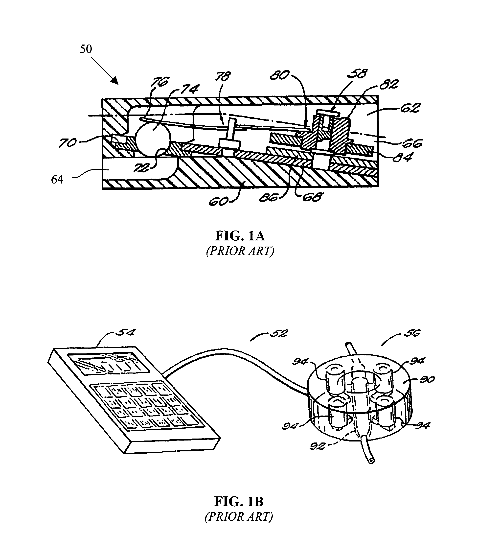
[0037] By way of introduction, FIG. 1A shows a prior art externally programmable shunt valve system 50. The shunt valve 50 is typically surgically implanted under the scalp of a patient. The shunt valve 50 includes a valve body 60 defining a chamber 62 with an inlet opening 64 and an outlet opening 66. When a fluid pressure at the inlet opening exceeds the predetermined threshold, fluid begins to flow through the shunt valve via the inlet and outlet openings 64, 66. A support plate 68 is disposed within the valve body 60 and includes an aperture 70 at one end that is provided with a valve seat 72. A ball 74 is adapted for sealing engagement with the valve seat 72. A first end 76 of a spring 78 biases the ball to the valve seat 72 to prevent fluid flow. The biasing force of the spring 78 is adjustable by varying the vertical position of the spring at a second end 80, which can be adjusted by means of a cam 82. The cam 82 includes a plurality of steps of varying vertical position with...


PUM


Abstract

An acoustic monitoring system that is able to verify the success or failure of the positional adjustment of a valve without the need for additional energy during non-invasive reprogramming is provided. The acoustic monitoring system includes a programmer for generating a sequence of commands to adjust the valve mechanism, and for receiving acoustic signals for analysis, a transmitter to implement the command and adjust the valve, and a sensor for detecting an acoustic signal generated from the valve during execution of the commands. A method for using the acoustic monitoring system is also provided.

Description

CROSS-REFERENCE TO RELATED APPLICATIONS [0001] This application is a continuation of U.S. patent application Ser. No. 10 / 328,748, filed on Dec. 23, 2002.STATEMENT REGARDING FEDERALLY SPONSORED RESEARCH [0002] Not Applicable. FIELD OF THE INVENTION [0003] The present invention relates to methods and devices for non-invasively monitoring the performance of implanted medical devices without requiring additional energy means such as x-ray, ultrasound, or telemetry. More specifically, the present invention relates to a method for detecting the activity of an implanted adjustable shunt valve using an acoustic monitoring device and system. BACKGROUND OF THE INVENTION [0004] Shunt systems for directing body fluid from one region to another are known in the medical field. One application for such a shunt system is in the treatment of hydrocephalus, a condition where cerebrospinal fluid collects in the ventricles of the brain of a patient. Cerebrospinal fluid is produced by the ventricular sy...

Claims


Application Information

Patent Timeline
IPC IPC(8): A61M1/00A61B7/00
CPCA61B2562/0204A61B7/005
Inventor TAYLOR, TERRI K.ROSENBERG, MEIRGUPTA, RAINUKAWILSON, STEPHEN F.OSTIGUY, PIERRE S.ROMNER, BERTILDEXTRADEUR, ALAN J.
Owner INTEGRA LIFESCI SWITZERLAND SARL
Why Eureka
Try Eureka