Front and rear firearm sights

a front and rear technology, applied in the field of front and rear firearm sights, can solve the problems that the sight which is largely bead sights mounted on the end of the barrel does not lend itself to law enforcement or military us

Inactive Publication Date: 2003-07-31
KAY IRA
View PDF0 Cites 60 Cited by
  • Summary
  • Abstract
  • Description
  • Claims
  • Application Information

AI Technical Summary

Problems solved by technology

Such sights which are largely bead sights mounted on the end of the barrel do not lend themselves to law enforcement or military use.

Method used


Image

  • Front and rear firearm sights
  • Front and rear firearm sights
  • Front and rear firearm sights

Examples


Embodiment Construction

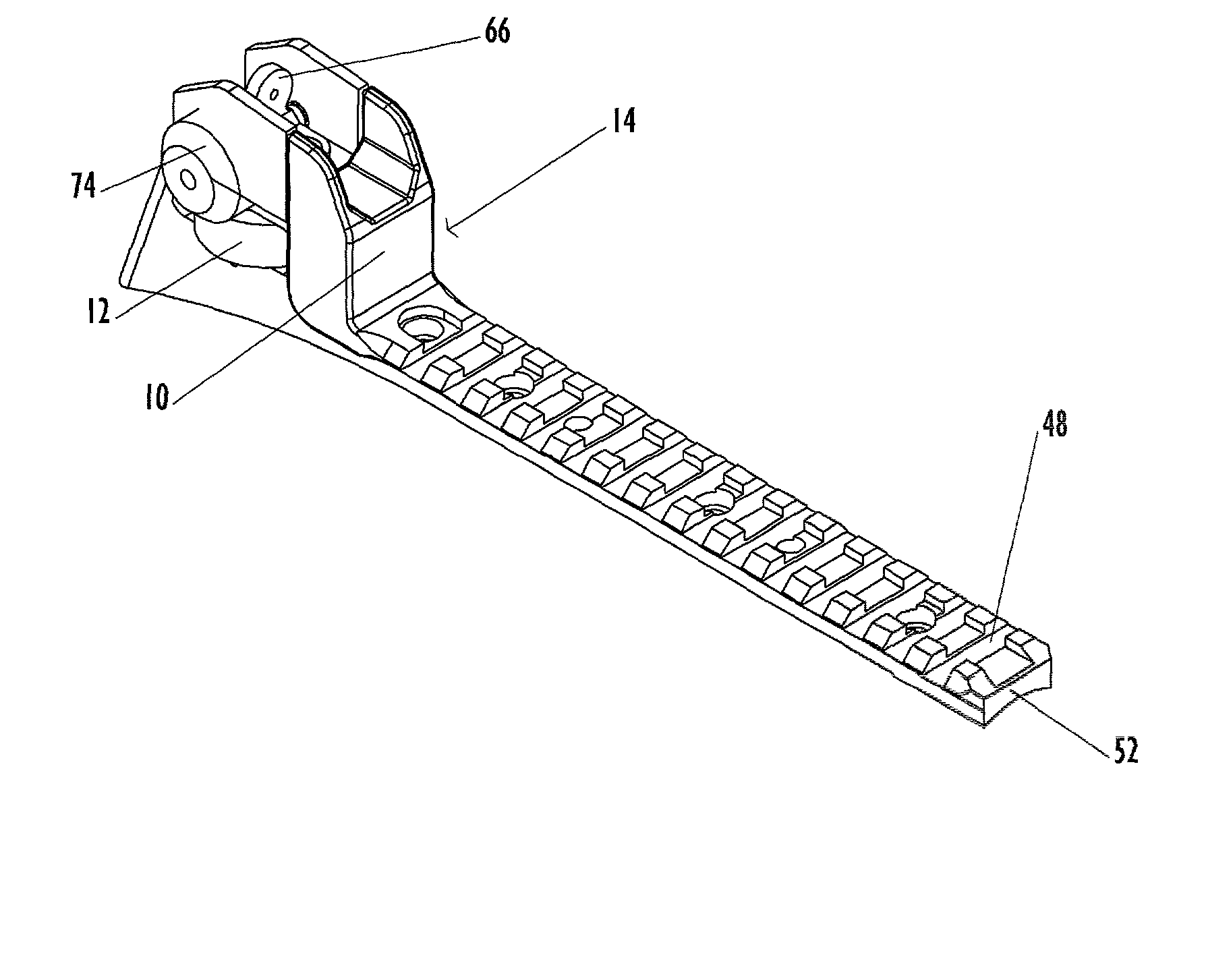
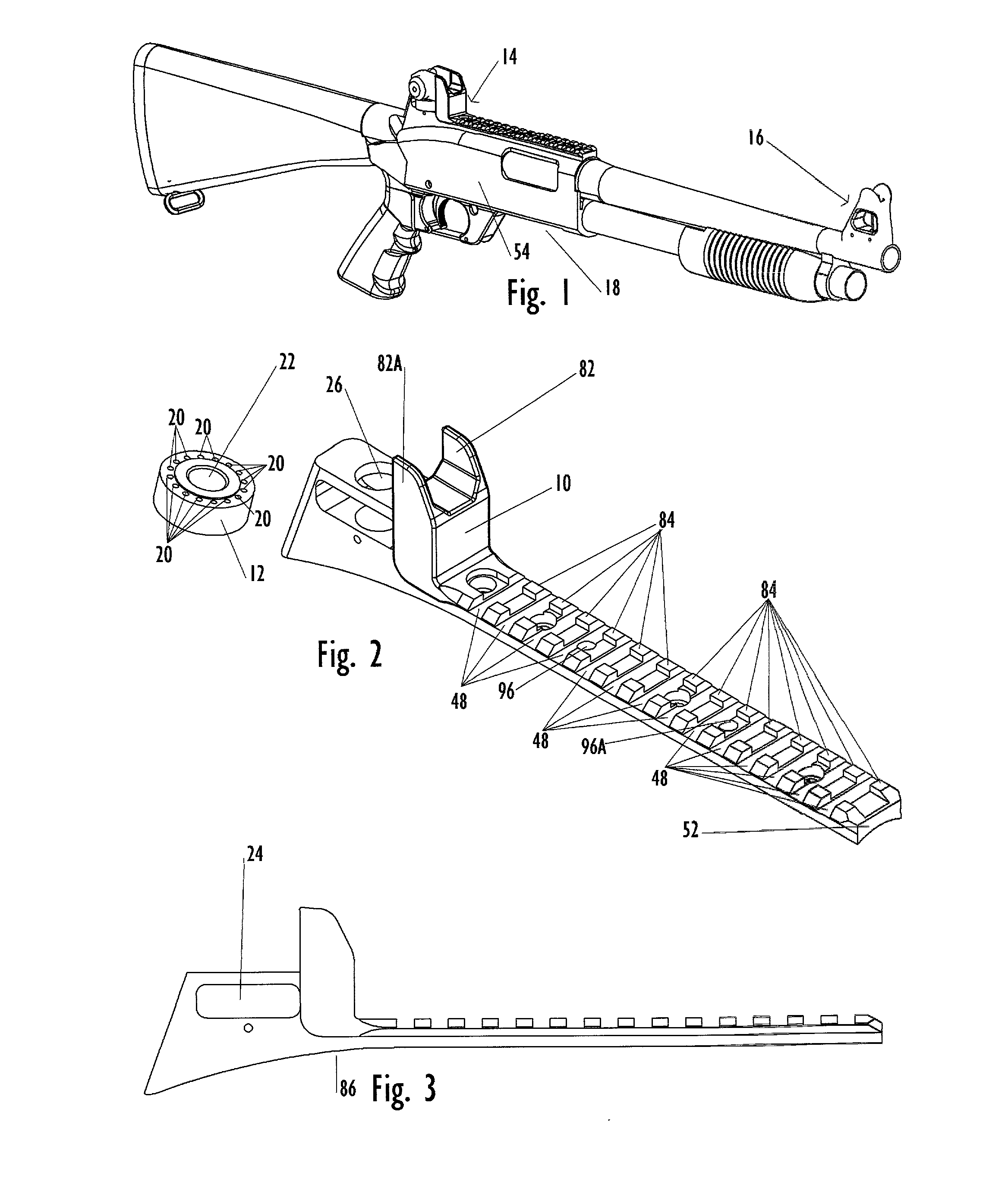
[0101] FIG. 1 is a perspective view which shows the front and rear sights of the preferred embodiment of the present invention which includes a rear sight assembly 14, and a front sight assembly 16, mounted to a shotgun 18. FIG. 2 shows a rear sight base 10, and a rear sight elevation drum 12, in a prespective view. Shown is the rear sight base 10 which has protective wing 82, and protective wing 82A, and extending from a front 52 surface a M-1913 style rail which extends towards the protective wings 82, and 82A of the rear sight base 10. Shown a interrupted transverse rib 84. Said rear sight base 10 contains a plurality of interrupted transverse ribs 84, spaced from front to back according to M-1913 specification, and commonly referred to as a "Picatinny Rail". Said interrupted transverse ribs 84 are separated by a crosscut(s) 48. FIG. 2 shows elevation drum indexing bore 20 which are coaxially aligned around the threaded bore 22 of the rear sight elevation drum 12. Shown in FIG. 2...


PUM


Abstract

The front and rear sights for shotguns which are the object of the present invention provide the use of M16 / M4 style sights within sight bases which can be affixed to the receiver and barrel of a shotgun. An enhanced level of precision as well as familiarity is imparted to shotguns which employ sights of the configuration described within the present invention. The addition of a M-1913 style rail base to the rear sight assembly brings the added benefit of the ability to add an additional sighting collimator to the rear sight assembly in terms of a reflex, or refractory optical sight which conveys the benefit of a co-witnessed sight alignment. The use of M16 / M4 style sights which have proved the test of time in military deployments from the 1960's until the present time bring an operationally sound modality to shotguns that are tactically employed.

Description

BACKGROUND--FIELD OF INVENTION[0001] This invention relates to firearm sights, and shotguns in particular, whereby M4 / M16 style sights can be utilized in conjunction with with an integral mounting rail.BACKGROUND--DESCRIPTION OF PRIOR ART[0002] Traditionally shotguns have been employed for wing shooting activities due to the pattern of projectiles that they produce which increase probability of hit upon moving aerial targets. With current law enforcement practice employing shotguns for applications where previously carbines would have been utilized, there is a cross-over use for a shotgun where it now is used in a manner similar to a carbine or rifle. With the demands for precision rifle style of fire as opposed to an area of fire, the need for precision tactical sights that perform similarly to those on a rifle or carbine is of paramount importance. Conventional shotgun sights are very rudimentary and predicated on a perfect mount of the firearm to the shooter so that they become u...

Claims


Application Information

Patent Timeline
Patent Type & Authority Applications(United States)
IPC IPC(8): F41G1/033F41G1/08F41G1/17
CPCF41G1/033F41G1/17F41G1/08
Inventor KAY, IRA
Owner KAY IRA
Why Eureka
Try Eureka