
Apparatus & method for shimming surfaces

a technology of shimming surface and apparatus, applied in the field of shimming, can solve the problems of prone to breakage or splintering, dangerous and costly damage to the apparatus, and undesirable shimming surface breakag

Inactive Publication Date: 2003-08-07
HOLDER BRUCE
View PDF0 Cites 20 Cited by
  • Summary
  • Abstract
  • Description
  • Claims
  • Application Information

AI Technical Summary

Problems solved by technology

However, heretofore, a problem with shims is that they tend to break or splinter when they are driven between the two surfaces.
The breaking of shims during the process of trying to adjust the spatial relationship between, for example a door and a frame member of a house, is inconvenient and a source of frustration for the person using the shim.
In addition, the undesirable breakage of shims can be dangerous and costly.

Method used


Image

  • Apparatus & method for shimming surfaces
  • Apparatus & method for shimming surfaces
  • Apparatus & method for shimming surfaces

Examples


Embodiment Construction

[0020] While the invention is susceptible to various modifications and alternative forms, a specific embodiment thereof has been shown by way of example in the drawings and will herein be described in detail. It should be understood, however, that there is no intent to limit the invention to the particular form disclosed, but on the contrary, the intention is to cover all modifications, equivalents, and alternatives falling within the spirit and scope of the invention as defined by the appended claims.

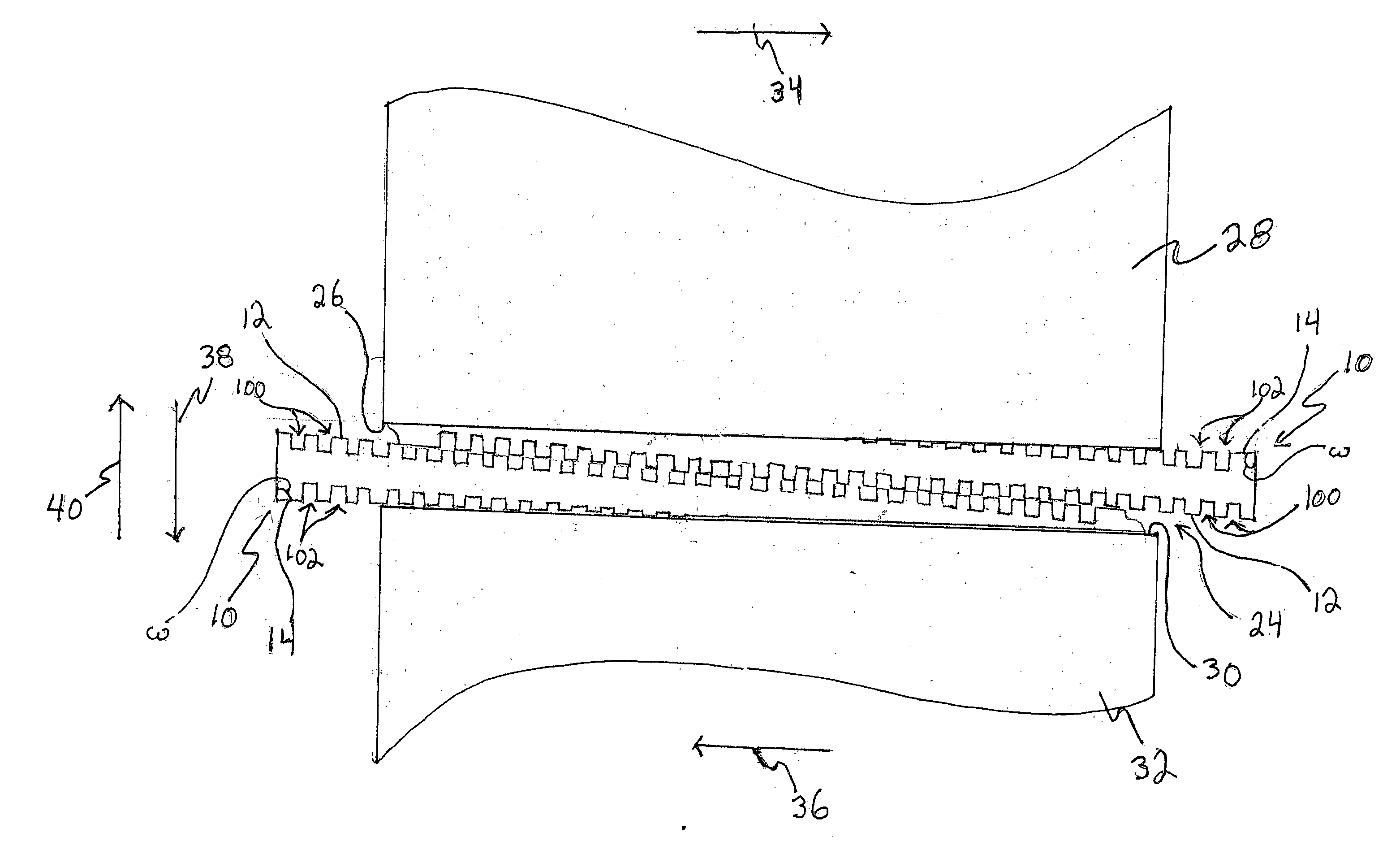
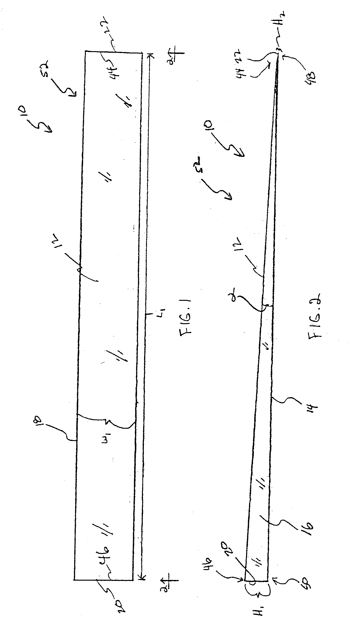
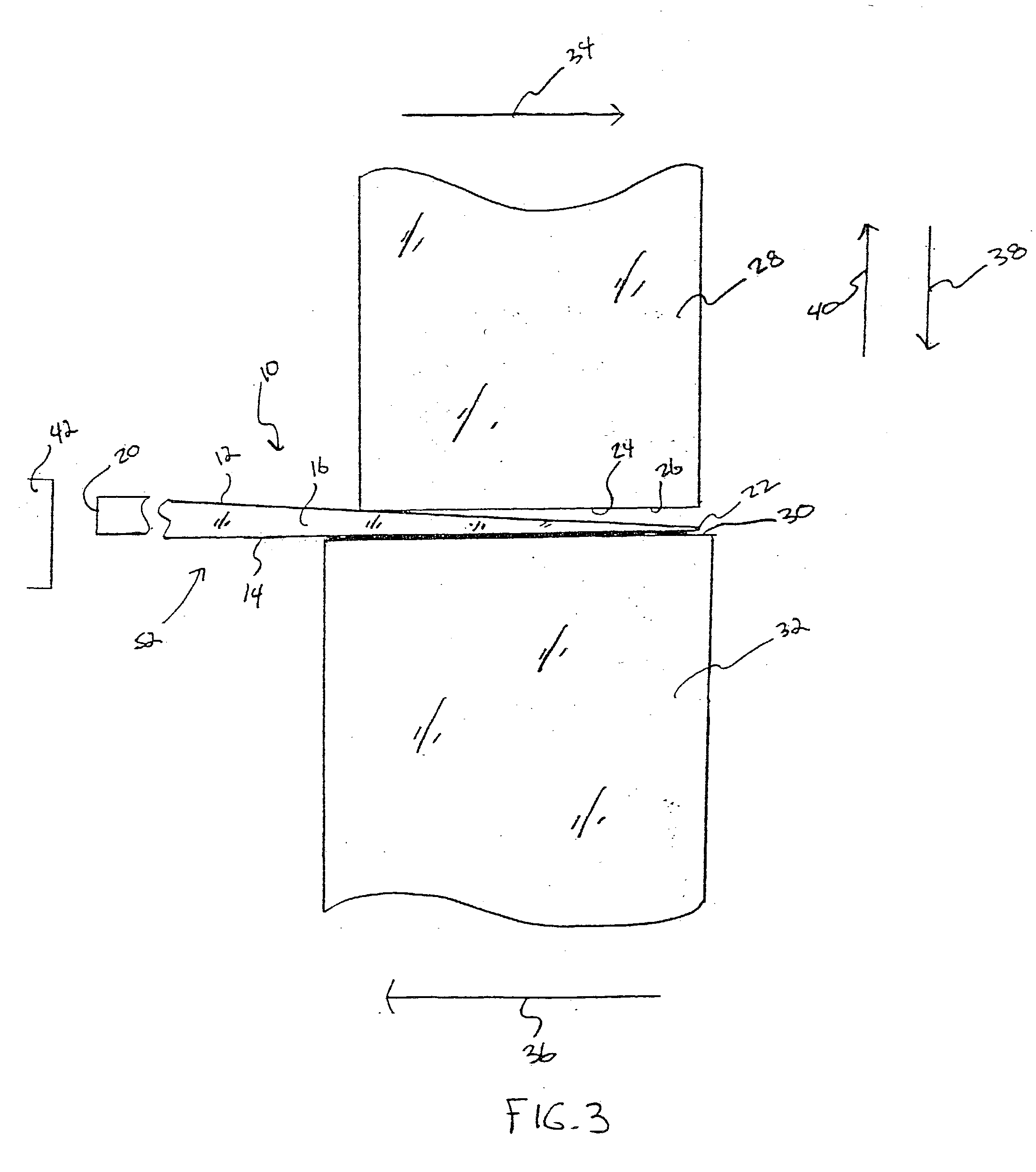
[0021] Referring now to FIGS. 1 and 2, there is shown a shim 10 which incorporates the features of the present invention therein. Shim 10 includes a body member 52. Body member 52 includes a top wall segment 12 having an end 44 and an end 46. Body member 52 also includes an end wall segment 22 attached to and extending from end 44 of top wall segment 12. Body member 52 further includes an end wall segment 20 attached to and extending from end 46 of top wall segment 12. Body member 52 s...


PUM


Abstract

A shim is disclosed. The shim includes a body member having (i) a top wall segment having a first end and a second end, (ii) a first end wall segment attached to and extending from the first end of the top wall segment, (iii) a second end wall segment attached to and extending from the second end of the top wall segment, and (iv) a bottom wall segment having a third end and a fourth end, the third end of the bottom wall segment being attached to the first end wall segment, and the fourth end of the bottom wall segment being attached to the second end wall segment. The top wall segment, the first end wall segment, the second end wall segment and the bottom wall segment are all made from a plastic material. Additionally, the shim may include a plurality of latitudinal apertures.

Description

[0001] This application is a Continuation-in-Part of U.S. patent application Ser. No. 10 / 068,189 which was filed on Feb. 05, 2002 and which is hereby incorporated by reference herein.TECHNICAL FIELD OF THE DISCLOSURE[0002] The present invention generally relates to a shim and an associated method of adjusting the spatial relationship between a first surface and a second surface. The present invention particularly relates to a shim having a body member made from a plastic material and an associated method of adjusting the spatial relationship between a first surface and a second surface with the shim.BACKGROUND OF THE DISCLOSURE[0003] Typically, a shim is a thin piece of wood which is used to adjust the spatial relationship between two surfaces. For example, a shim can be placed in between a surface defined on a frame member of a door and a surface defined on a frame member of a house. Once the shim is positioned in the above described manner, a tool, such as a hammer, can be utilize...

Claims


Application Information

Patent Timeline
IPC IPC(8): B65D65/28E04F13/08E04F21/00E06B1/60F16B43/00F16M7/00
CPCE04F13/0853E04F21/0007Y10T428/15F16B43/00F16M7/00E06B1/6069E04F21/0015
Inventor HOLDER, BRUCE
Owner HOLDER BRUCE
Learn More