Vending machine for dispensing cans & bottles with stop member

a technology of canning machine and stop member, which is applied in the direction of instruments, apparatus for dispensing discrete objects, de-stacking objects, etc., can solve the problems of increasing both cost, complexity and service related problems associated with their design, and difficult and challenging problems

Inactive Publication Date: 2003-08-07
THOMAS PLASTICS
View PDF0 Cites 10 Cited by
  • Summary
  • Abstract
  • Description
  • Claims
  • Application Information

AI Technical Summary

Benefits of technology

0019] The above and related objects are achieved by providing a vending machine having a plurality of racks therein for dispensing products. Each rack within such vending machine has multiple product dispensing racks wherein each rack comprises a vertical, rectilinear channel defined by pairs of opposing panels or walls. Each channel of each rack has an open end at the top end thereof and closed end at the bottom end thereof, wherein the closed end includes a movable platform for support of product and an open end for dispensing product in response to consumer demand. The open end of the rack is further provided with at least one non-mechanical stop for control of the dispensing of products from such racks in response to customer demand. In the preferred embodiments of this invention, the nonmechanical stop is formed of a resilient deformable material (e.g. natural or synthetic rubber or an equivalent elastomer), and includes means for engagement of a complimentary recess or slot in the opposing panels which define the vertical channel of the product dispensing rack. In the preferred embodiments of this invention, more than one the stop or gate is provided at the open end of each racks within the vending machine, so as to provide equal pressure to each side of the container within the rack and, thus, assist in maintaining its proper orientation of the containers within the rack.

Problems solved by technology

Because the containers (other than cans) generally have a characteristic shaped indicative of a trade dress or design, their retention within the vending machine, specifically, within vertical storage channels, can present difficulties and challenges.
Moreover, the relative complexity in such mechanisms and the controls for such mechanisms necessarily increases both cost, complexity and service related problems associated with their design and use.

Method used


Image

  • Vending machine for dispensing cans & bottles with stop member
  • Vending machine for dispensing cans & bottles with stop member
  • Vending machine for dispensing cans & bottles with stop member

Examples


Embodiment Construction

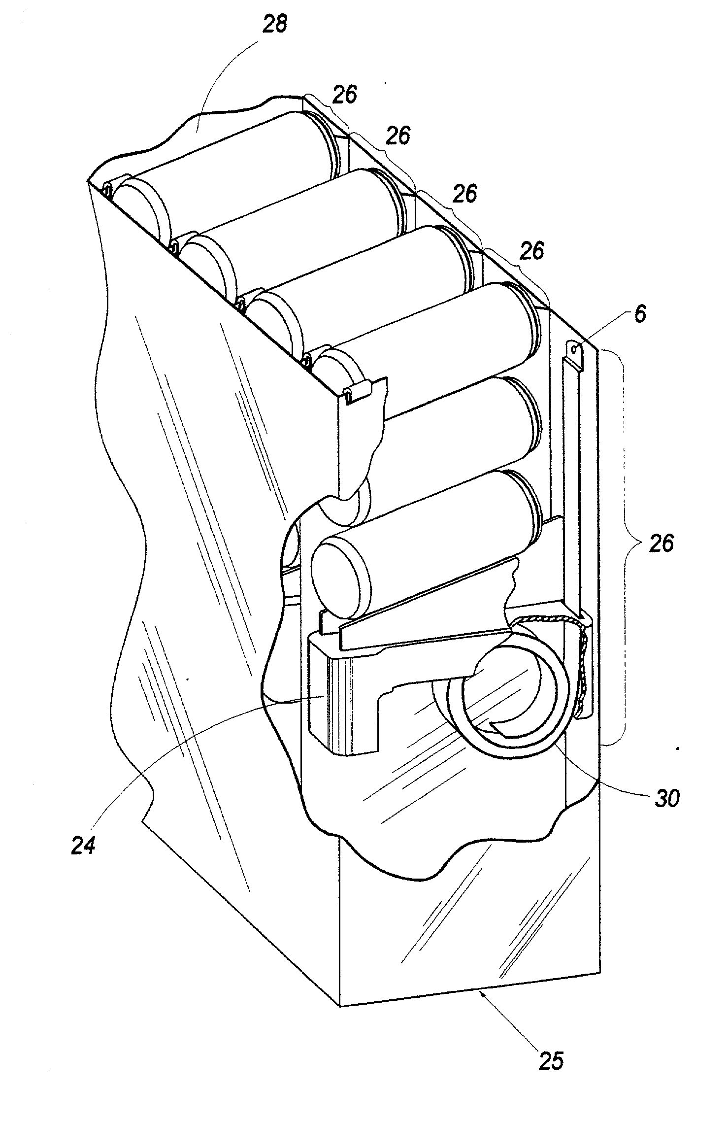
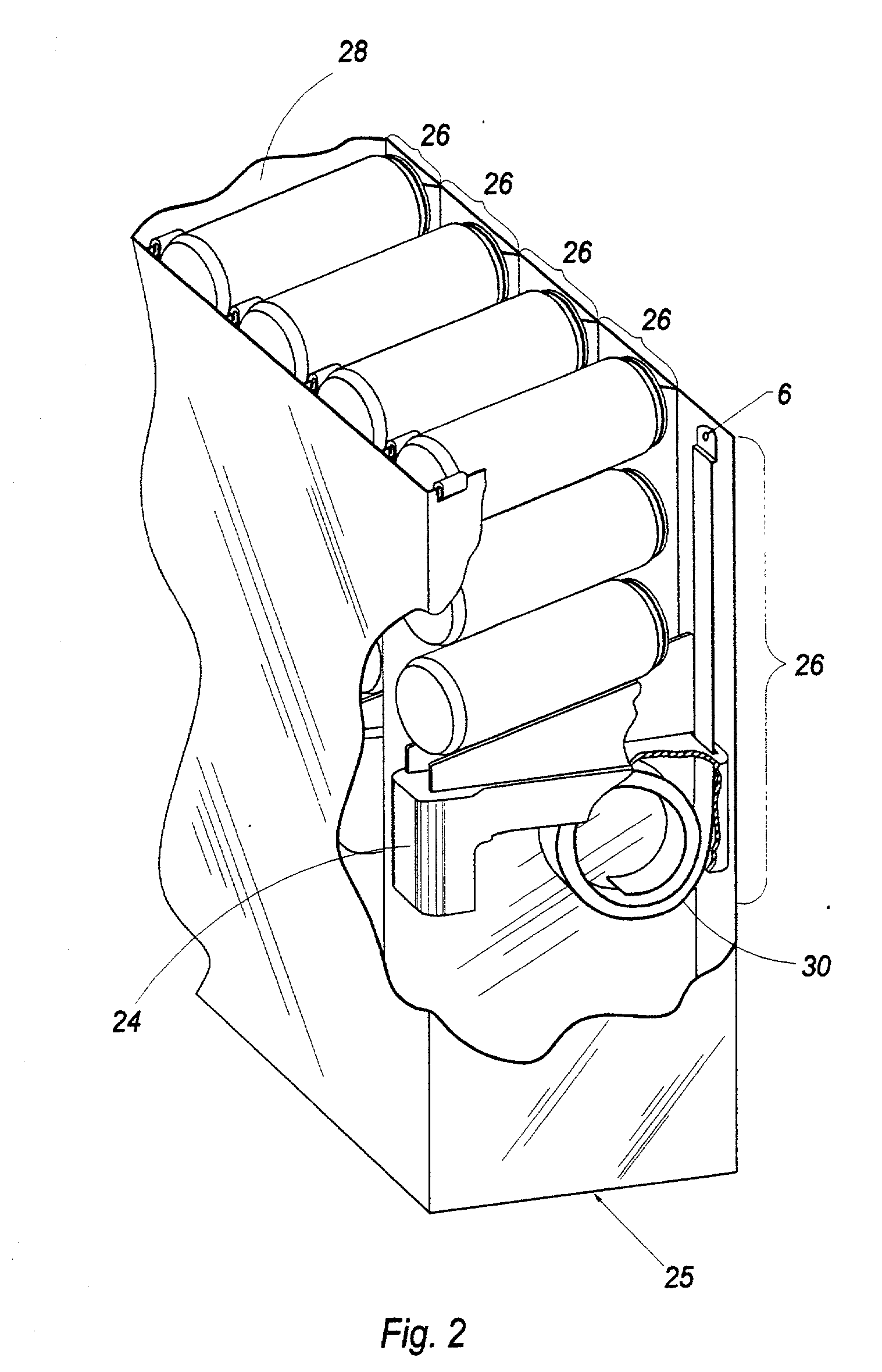
[0025] The figures which accompany this application, and referenced herein, depict a representative vending machine of this invention. In the embodiments of this invention illustrated in these figures, one or more components of the vending machine may appear in more than one figure. Accordingly, components which are common to more than one figure are assigned a common reference numeral for continuity of description and ease of understanding.

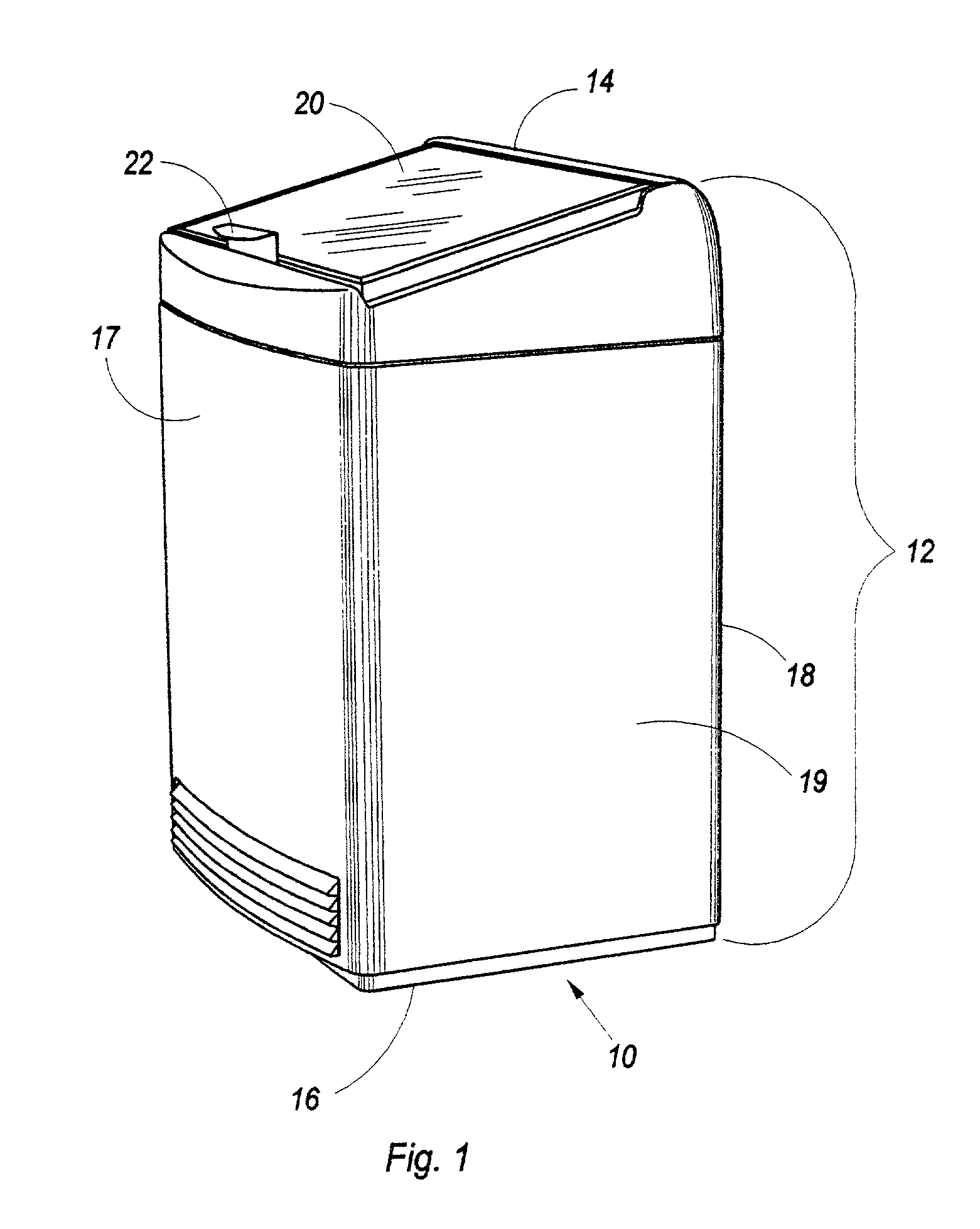
[0026] In FIG. 1, a vending machine (10) is illustrated comprising a cabinet (12) having three dimensions, including a top (14), a bottom (16) and four sides (front (17), back (18), left side (19) and right side (not shown). In the embodiment illustrated in FIG. 1, the top (14) of the cabinet is provided with a hinged access door (20) to permit opening of the cabinet (12) to gain access to its contents. The access door (20) is shown in the locked or closed position. A latch (22) is associated with the top (14) of the cabinet (12) to disengage the...


PUM


Abstract

An improved vending machine having a plurality of vertically inclined racks therein for dispensing products is disclosed. Each rack within such vending machine has an open end and closed end, wherein the open end thereof is provided with a mechanical stop or gate having essentially no mechanical moving parts, for control of the dispensing of products from such racks in response to customer demand for product from such rack. In the preferred embodiments of this invention, the mechanical stop or gate is formed of a resilient deformable material (e.g. natural or synthetic rubber or an equivalent elastomer), and includes means for engagement of a complimentary recess or slot at the end of the product dispensing rack. In the preferred embodiments of this invention, more than one stop or gate is provided at the open end of each rack within the vending machine, so as to provide equal pressure to each side of the container within the rack and thus assist in maintaining the proper orientation of the containers within the rack.

Description

[0001] 1. Field Of The Invention[0002] This invention relates to an article of manufacture. More specifically, this invention is directed to an improvement in vending machines designed for the storage and dispensing of containers, preferably beverage containers in the form of cans or bottles.[0003] 2. Background Of Invention[0004] Vending machines generally, and beverage vending machines, in particular, are of two basic designs and include a product storage cabinet (with or without refrigeration). These two basis designs include:[0005] (a) Means for gravity-feeding product dispensers, wherein the containers are positioned above the dispensing window and incrementally released so as to effect dispensing thereof, or, alternatively,[0006] (b) Means for elevator-feeding product dispensers, wherein the containers are loaded upon a platform disposed within a storage channel that is inclined from the horizontal, the platform is advanced upwardly, relative to the horizontal plane and within...

Claims


Application Information

Patent Timeline
Patent Type & Authority Applications(United States)
IPC IPC(8): G07F11/32
CPCG07F11/32
Inventor BEAUREGARD, RONALD H.
Owner THOMAS PLASTICS
Why Eureka
Try Eureka