Device for installing an anchor in a bone

a technology for installing an anchor and a bone, which is applied in the field of devices for installing an anchor in the bone, can solve the problems of difficult to secure the suture to the bone material, and difficult to positively locate the anchor in the desired position

Active Publication Date: 2003-08-14
STEWART KENNETH +1
View PDF2 Cites 60 Cited by
  • Summary
  • Abstract
  • Description
  • Claims
  • Application Information

AI Technical Summary

Problems solved by technology

The anchor allows a suture to be secured to it, whereas it would otherwise be difficult to secure the suture to the bone material.
The prior devices have the problem that threading or advancing an expansion cone or ram into a proximally-facing opening of the anchor body has the effect of pushing the anchor body deeper into the borehole in the bone where it is more difficult to connect in a predictable way with the suture.
It is thus difficult to positively locate the anchor in a desired position with its proximal end aligned with the bone surface.

Method used


Image

  • Device for installing an anchor in a bone
  • Device for installing an anchor in a bone
  • Device for installing an anchor in a bone

Examples


Embodiment Construction

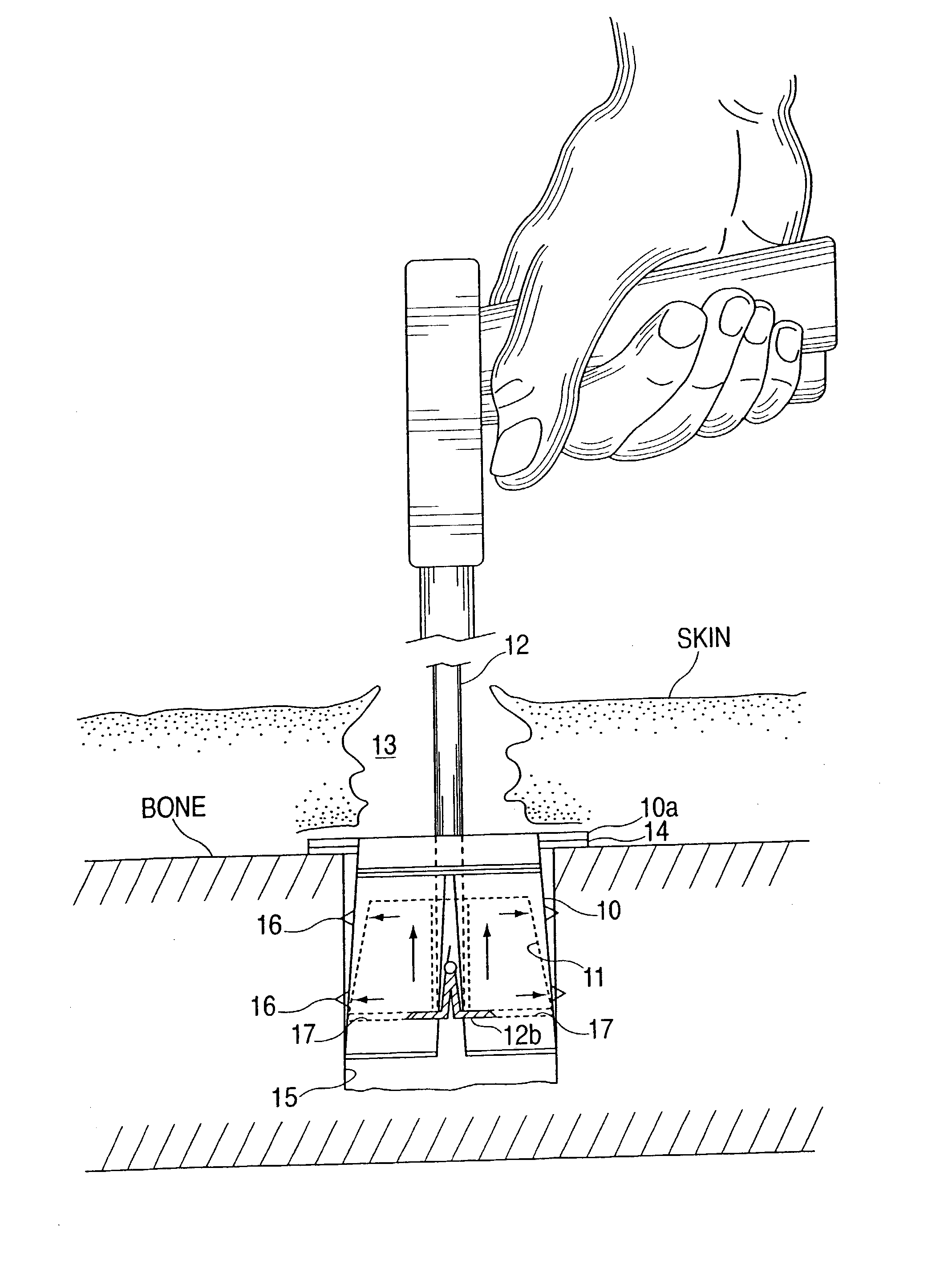
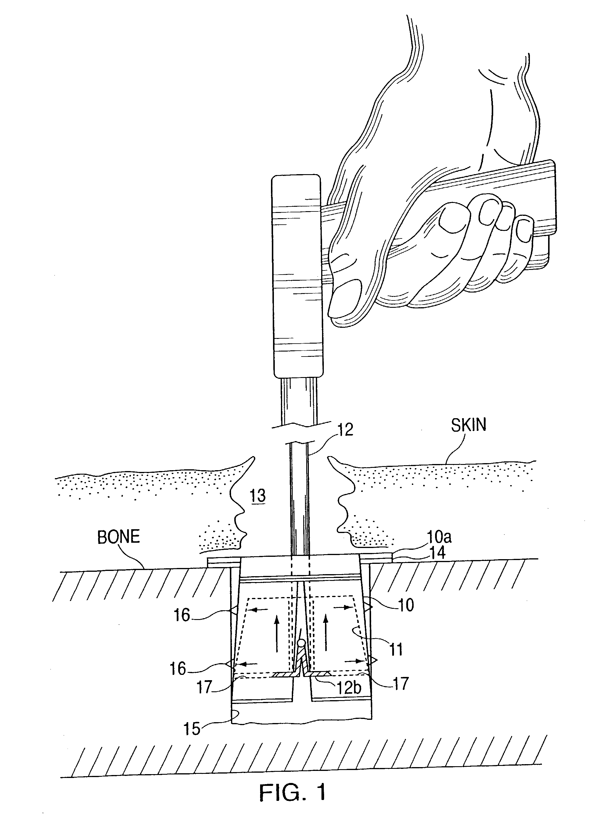
[0027] Referring to FIG. 1, a device for surgically installing an anchor in bone includes an anchor body 10, an expansion member 11, and an installation tool 12. The anchor body 10 is installed in a patient's bone as a terminal for fixation of fractures or joints or to repair or attach tendons or ligaments to the bone. An incision 13 is first made through the patient's skin (SKIN) or tissue to expose the work area of the bone (BONE). A borehole 15 is drilled into the bone for installation of the anchor body 10 therein. The anchor body 10 has expandable side walls with a tapered shape, with a narrower proximal end thereof(toward the top of the figure) to face outwardly from the borehole in the bone and a wider distal end thereof (toward the bottom of the figure) to be inserted in the borehole. The anchor body 10 may have an upper anchor plate 10a that overlies or is adhered with an adhesive layer 14 over the borehole in order to positively locate the anchor unit aligned with the surf...


PUM


Abstract

A device and method for installing an anchor in a bone of a patient employs an anchor body having expandable side walls in a tapered shape with retention members on their external surfaces, and an expansion member within the anchor body which is pulled to an engaged position where it presses on the inside of the side walls to expand them outwardly to engage the retention members with the bone walls of a borehole in which the anchor body is inserted. Preferably, the anchor body is sectioned by slits to form expandable side wall sections below an expansion joint or deformation wrinkle. The side walls have containment ring sections at their distal ends for retaining the expansion member inside the anchor body. The expansion member may be formed as a conical plug with a central aperture and tab recesses on its underside for insertion of an elongated scissors-type instrument with movable prongs that engage into the tab recesses of the expansion plug. Alternatively, the expansion tool can have a threaded tip for threading in a threaded bore formed in the expansion plug. The anchor body may have guide ribs that fit in slot recesses in the expansion plug member for guiding its movement. The guide ribs may be formed as hollow tubes to allow insertion and squeezing together of the straight ends of a removal tool to dislodge the expansion member in the event removal is desired. The retention members may be formed as annular cutter blades. The anchor body may have an anchor plate at its proximal end to align and bond the anchor body with the bone surface.

Description

[0001] This U.S. patent application claims the priority of U.S. Provisional Application No. 60 / 355,215 filed on Feb. 8, 2002.[0002] This invention generally relates to surgically installing an anchor in a bone of a patient, and more particularly, to an improved device that allows for quick and easy installation of an anchor in the bone.BACKGROUND OF INVENTION[0003] Suture anchors are used to secure sutures to bones during joint reconstructive surgery or arthroscopic surgical procedures. The anchor allows a suture to be secured to it, whereas it would otherwise be difficult to secure the suture to the bone material. For example, suture anchors are used to connect ligaments or tendons to bones during knee, shoulder or elbow reconstruction or repair operations. A bone anchor must be easy to install and must remain firmly in place for the intended time. It must be able to resist withdrawal forces exerted by the attached suture, and must also be physically compatible with the bone struct...

Claims


Application Information

Patent Timeline
Patent Type & Authority Applications(United States)
IPC IPC(8): A61B17/04
CPCA61B17/0401A61B17/0482A61B2017/00862A61B2017/0438A61B2017/0414A61B2017/042A61B2017/0425A61B2017/0409
Inventor STEWART, KENNETHSWEENEY, THOMAS M. II
Owner STEWART KENNETH
Why Eureka
Try Eureka