Method for controlling array antenna equipped with a plurality of antenna elements, method for calculating signal to noise ratio of received signal, and method for adaptively controlling radio receiver

a technology of array antenna and antenna element, applied in the direction of direction finders using radio waves, pulse techniques, instruments, etc., can solve the problems of complex circuit for adaptive control, inability to calculate the ratio in real time for the received signal, and inability to use methods

Inactive Publication Date: 2003-08-21
ATR ADVANCED TELECOMM RES INST INT
View PDF4 Cites 43 Cited by
  • Summary
  • Abstract
  • Description
  • Claims
  • Application Information

AI Technical Summary

Problems solved by technology

However, there has been such a problem that the method has not been able to be used when the transmitted radio signal is modulated by a modulation method that includes amplitude modulation.
However, the above-mentioned prior art example needs a reference signal such as a learning sequence signal, and is required to make the reference signals coincide with each other on both the transmission side and the reception side, and this leads to such a problem that the circuit for adaptive control has been complicated.
However, it has been unable to calculate the ratio in real time for the received signal.

Method used


Image

  • Method for controlling array antenna equipped with a plurality of antenna elements, method for calculating signal to noise ratio of received signal, and method for adaptively controlling radio receiver
  • Method for controlling array antenna equipped with a plurality of antenna elements, method for calculating signal to noise ratio of received signal, and method for adaptively controlling radio receiver
  • Method for controlling array antenna equipped with a plurality of antenna elements, method for calculating signal to noise ratio of received signal, and method for adaptively controlling radio receiver

Examples


third preferred embodiment

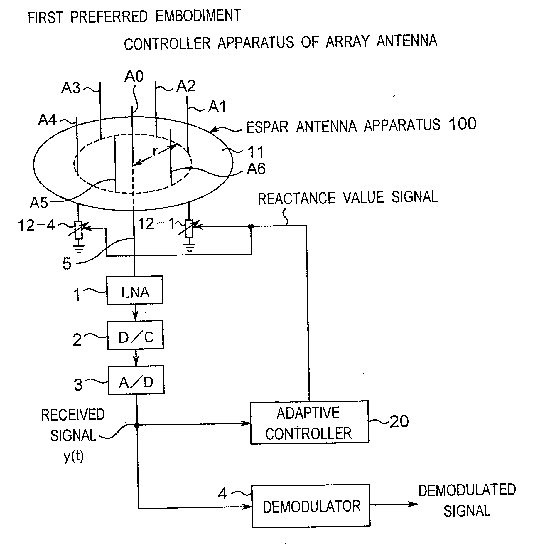
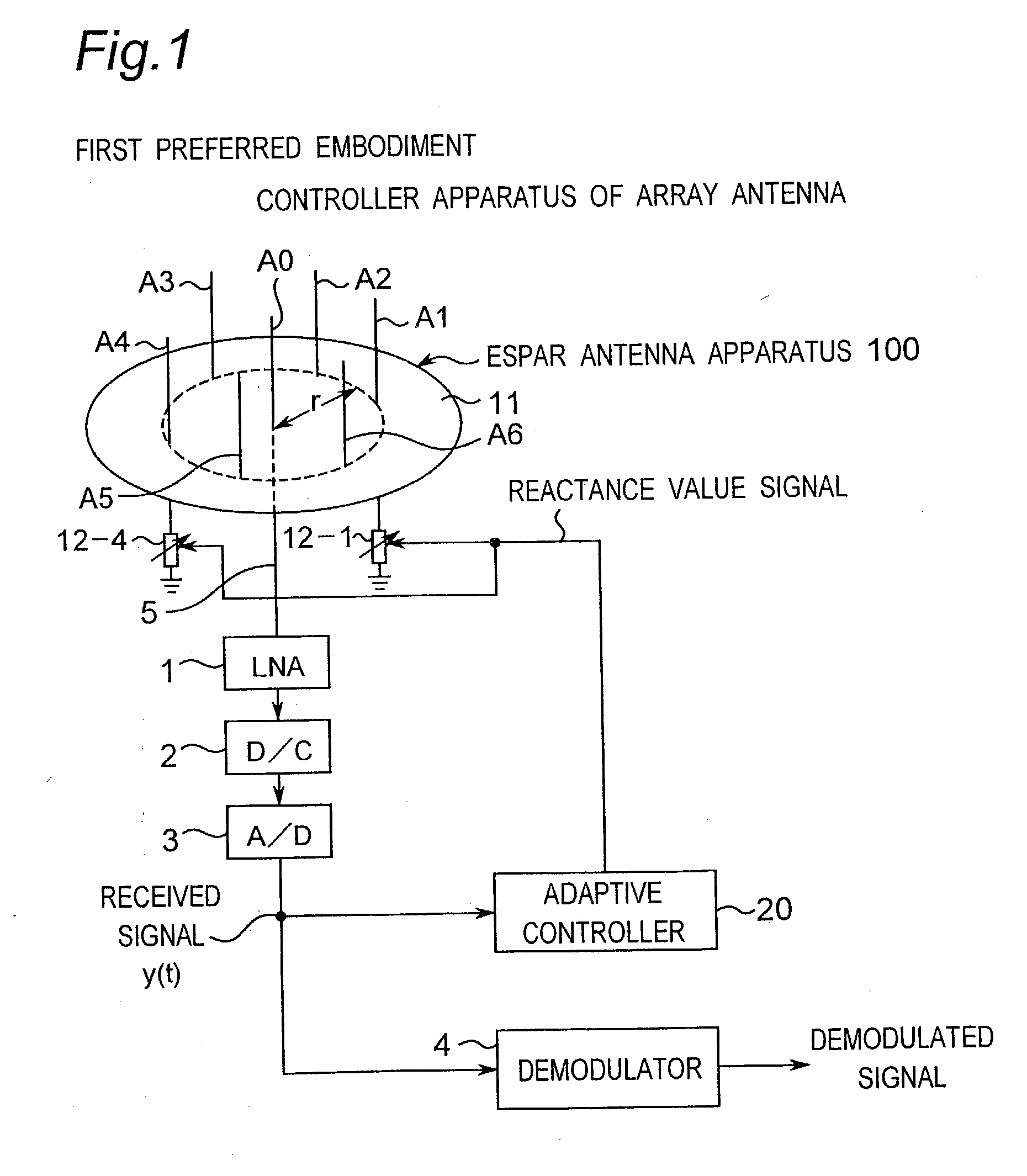
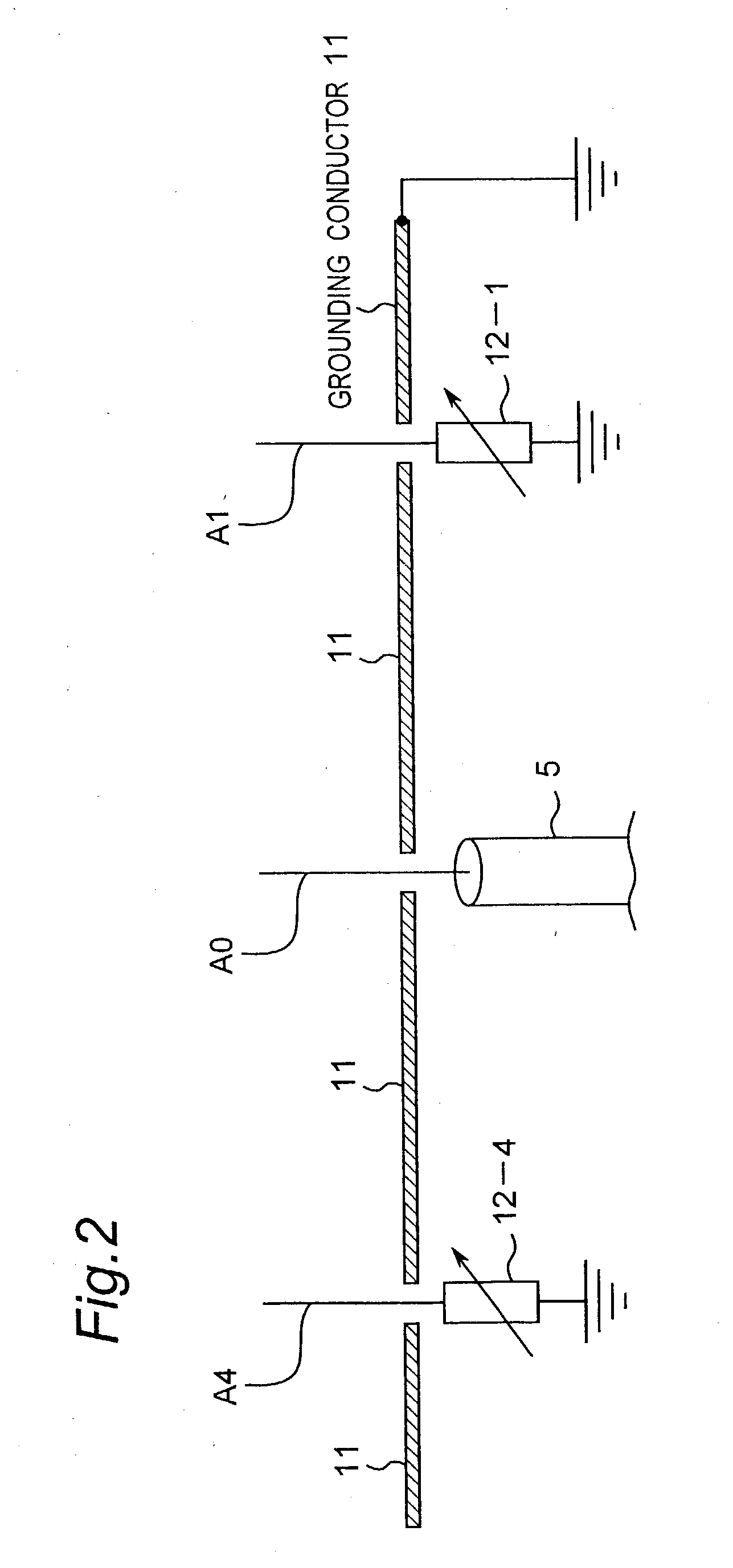
[0180] FIG. 10 is a block diagram showing a construction of a controller apparatus of an array antenna according to a third preferred embodiment of the present invention. As shown in FIG. 10, the controller apparatus of the array antenna of the present preferred embodiment is constructed of an ESPAR antenna apparatus 100 provided with one radiating element A0 and six parasitic elements A1 to A6 and an adaptive controller 20a and is particularly characterized in that the adaptive controller 20a is provided in place of the adaptive controller 20 of the first preferred embodiment.

[0181] In this case, as a radio signal which is transmitted from the transmission side and used for the adaptive control on the reception side, as described in detail later, there is used, for example, a radio signal modulated by the modulation method that includes digital amplitude modulation such as multi-valued quadrature amplitude modulation (QAM: Quadrature Amplitude Modulation) such as 16QAM, 64QAM and 2...

fourth preferred embodiment

[0199] FIG. 13 is a block diagram showing a construction of a controller apparatus of an array antenna according to a fourth preferred embodiment of the present invention. This fourth preferred embodiment is characterized in that an adaptive controller 60a is provided in place of the adaptive controller 60 of the second preferred embodiment.

[0200] In the present preferred embodiment, the adaptive controller 60a calculates phase shift control voltages v.sub.p (p=1, 2, . . . , P) corresponding to the amounts of phase shift of variable phase shifters 53-1 to 53-P for directing the main beam of the array antenna 50 in the direction of the desired wave and directing nulls in the directions of the interference waves on the basis of the received signal y(t) so that the value of the above-mentioned objective function (the Equation (22)) becomes the minimum by executing processing similar to that of the adaptive control processing of FIG. 3 by using, for example, the steepest gradient method...

fifth preferred embodiment

[0208] FIG. 19 is a block diagram showing a construction of a controller apparatus of an array antenna according to a fifth preferred embodiment of the present invention. As shown in FIG. 19, the controller apparatus of the array antenna of the present preferred embodiment is constructed of an ESPAR antenna apparatus 100 provided with one radiating element A0 and six parasitic elements A1 to A6, a radio receiver 110 and an adaptive controller 120.

[0209] In this case, the transmitted radio signal is subjected to m-PSK modulation (m is herein an integer equal to or larger than two). The adaptive controller 120 is constructed of a digital calculator of, for example, a computer and is characterized in that the reactance values of variable reactance elements 12-1 to 12-6 for directing the main beam of the ESPAR antenna apparatus 100 in the direction of the desired wave and for directing nulls in the directions of the interference waves are calculated and set on the basis of the received ...


PUM


Abstract

Based on a received signal y(t) received by a radiating element of an array antenna including the single radiating element and a plurality of parasitic elements, an adaptive controller calculates and sets a reactance value of a variable reactance element for directing a main beam of the array antenna in a direction of a desired wave and directing nulls in directions of interference waves so that a value of an objective function expressed by only the received signal y(t) becomes either one of the maximum and the minimum by using an iterative numerical solution of a nonlinear programming method.

Description

[0001] 1. Field of the Invention[0002] The present invention relates to a method for controlling an array antenna apparatus, capable of changing a directive characteristic of the array antenna apparatus including a plurality of antenna elements. In particular, the present invention relates to a method for controlling an array antenna apparatus, capable of adaptively changing a directivity characteristic of an electronically controlled radiator array antenna apparatus (Electronically Steerable Passive Array Radiator (ESPAR) Antenna; hereinafter referred to as an ESPAR antenna). Further, the present invention relates to a method for calculating a signal to noise ratio of a radio receiver for calculating the signal to noise ratio of a received signal received by the radio receiver, and also, to a method for adaptively controlling a radio receiver utilizing the method for calculating the same.[0003] 2. Description of the Prior Art[0004] An ESPAR antenna of prior art is proposed in, for ...

Claims


Application Information

Patent Timeline
Patent Type & Authority Applications(United States)
IPC IPC(8): H01Q3/22H01Q3/24H01Q9/30H01Q19/32H01Q21/20
CPCH01Q3/22H01Q3/24H01Q21/20H01Q9/30H01Q19/32H01Q3/446
Inventor OHIRA, TAKASHI
Owner ATR ADVANCED TELECOMM RES INST INT
Why Eureka
Try Eureka