Multiple filter for use in a disc drive

a technology of disc drives and filters, applied in the direction of record information storage, electrical apparatus construction details, instruments, etc., can solve the problems between the head and the disc, and achieve the effect of increasing the chance of creating defects

Inactive Publication Date: 2003-08-21
SEAGATE TECH LLC
View PDF7 Cites 28 Cited by
  • Summary
  • Abstract
  • Description
  • Claims
  • Application Information

AI Technical Summary

Problems solved by technology

If the particle does not escape the shrouded disc area via the recirculation air flow, it will flow back toward the spindle a

Method used


Image

  • Multiple filter for use in a disc drive
  • Multiple filter for use in a disc drive
  • Multiple filter for use in a disc drive

Examples


Embodiment Construction

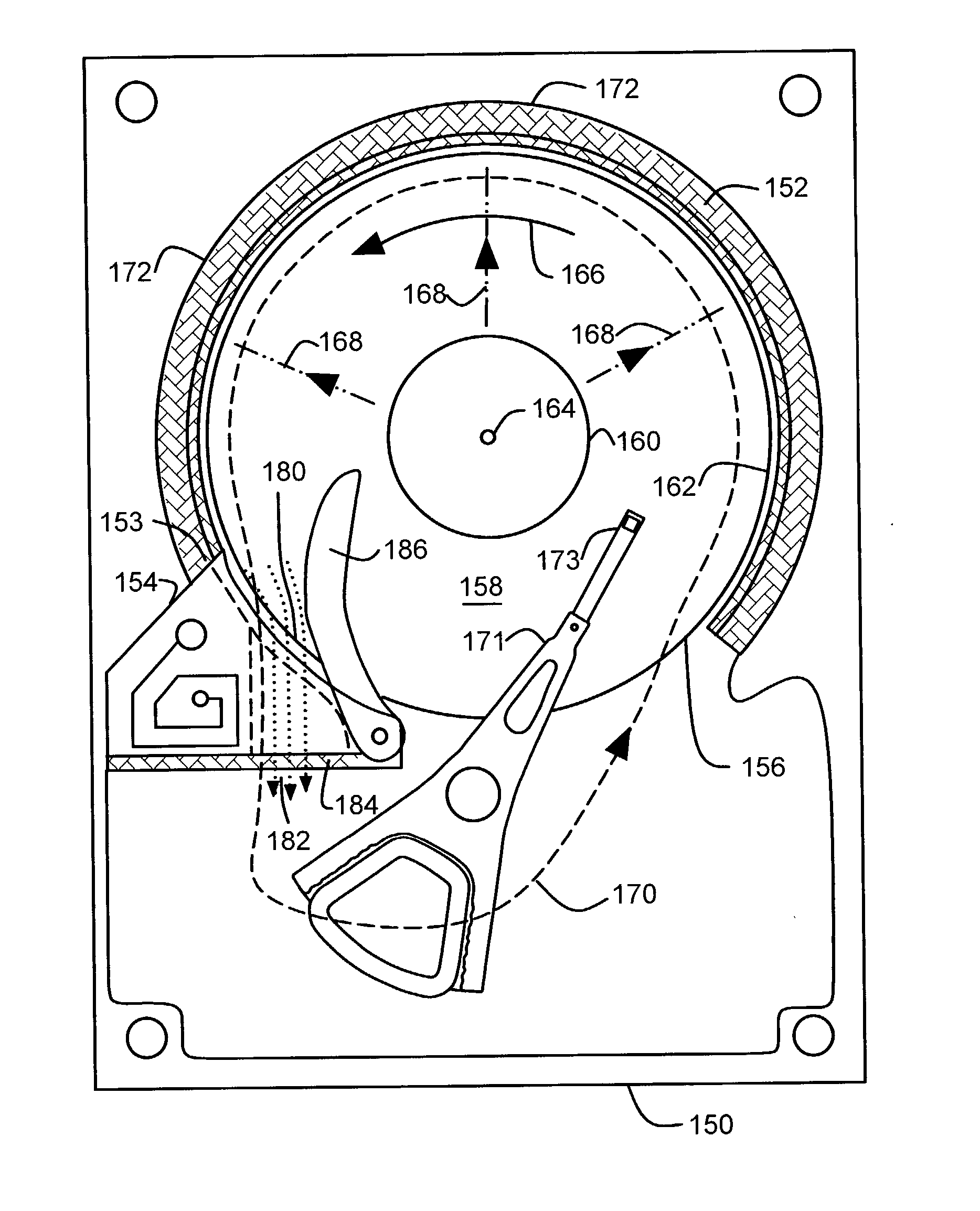
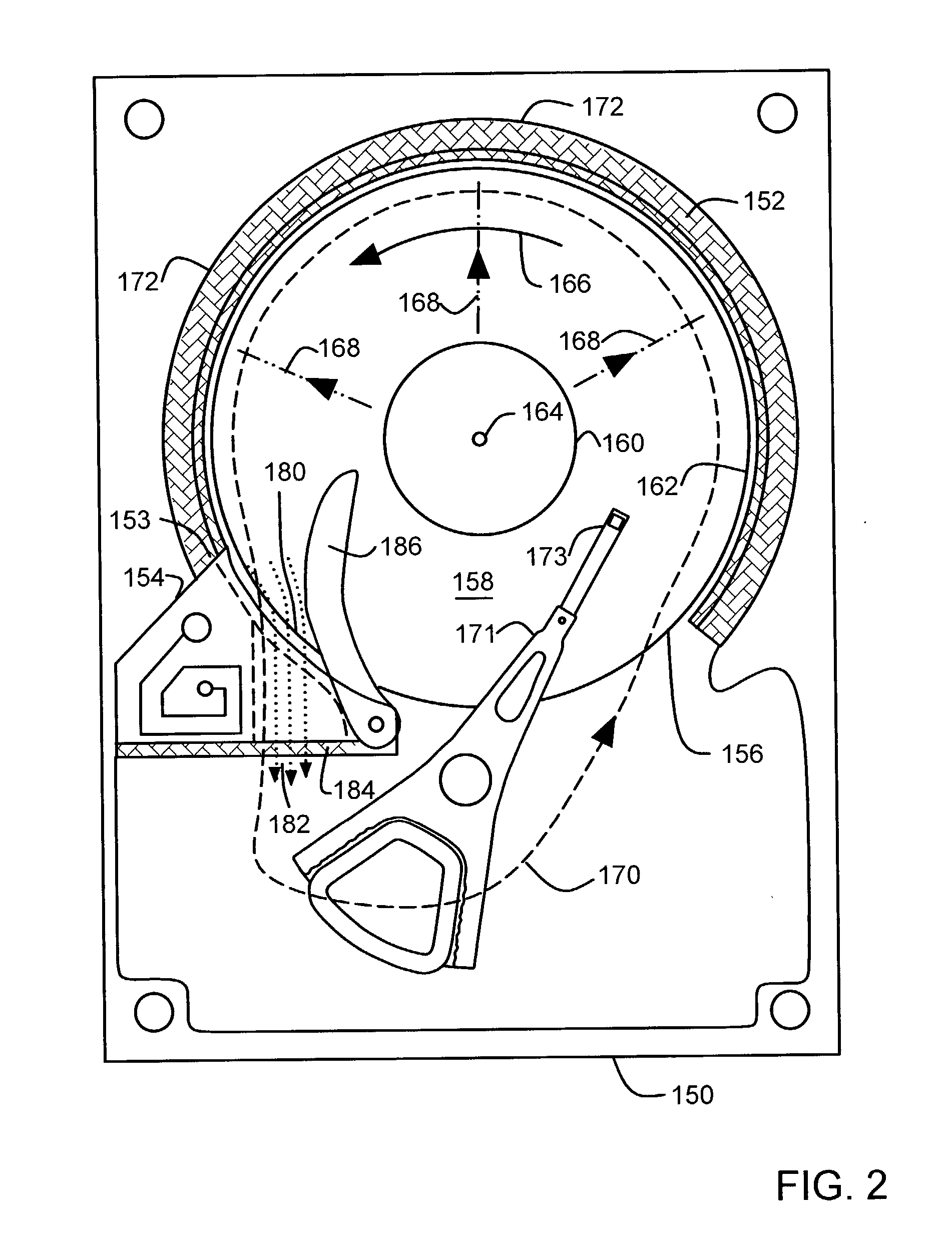
[0017] In the embodiments described below in FIGS. 2, 4-7, a disc drive has improved filtering performance. Lost data and / or mechanical damage due to particles in higher density disc drives is reduced. The disc drive includes a particle impact layer spaced apart from an outer disc edge, facing a radial air flow from a spinning disc in the disc drive. The particle impact layer is formed of a material that traps a first portion of the particles that is carried by the radial air flow. A filter is also disposed adjacent the outer disc edge. The filter comprises a recirculation filter element that traps a second portion of the particles that is carried by a recirculation air flow from the spinning disc.

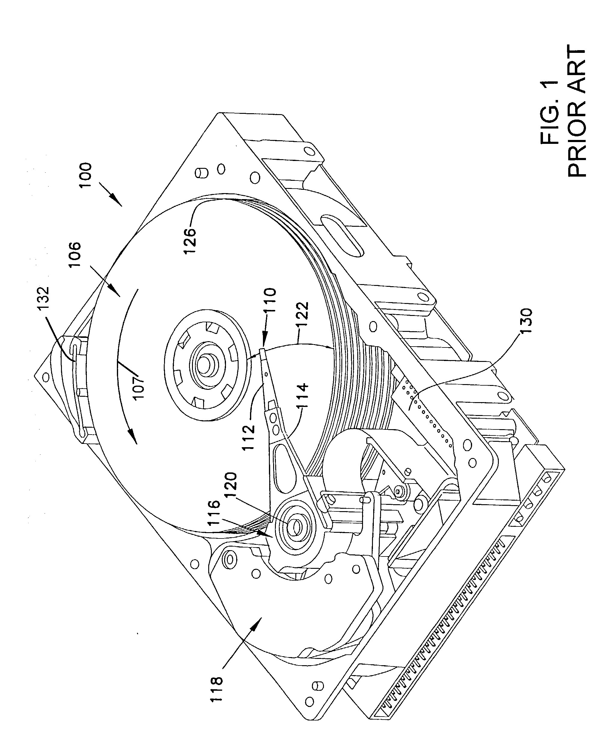
[0018] FIG. 1 illustrates a PRIOR ART embodiment of a disc drive storage device 100. Disc drive 100 includes a disc pack 126 having storage surfaces 106 that are illustratively layers of material (such as magnetic material or optically readable material). The disc pack 126 includes a stack...


PUM


Abstract

A layer of air adjacent a disc surface in a disc drive is subject to contamination by particles. The disc is spun, inducing a radial air flow and a recirculation air flow. A particle impact layer around an outer disc edge traps a first portion of the particles carried by the radial air flow. A filter adjacent the outer disc edge includes a recirculation filter element that traps a second portion of the particles carried by the recirculation air flow. STL 10692

Description

[0001] This application claims priority benefits from U.S. Provisional Application No. 60 / 359,278 titled "Shroud Filter for Disc Drive, "filed Feb. 20, 2002.[0002] The present invention relates generally to methods and components for reducing airborne particles inside data storage disc drives. In particular, the present invention relates to arrangements for filtering particles that can cause loss of data or damage to the disc drive.[0003] Particulates on a surface of a disc in a disc drive can interfere with the operation of a read / write head flying over the disc surface. As the disc spins, air flow tends to move particulates so that a particle passes between a read / write head and a disc, resulting in loss of data or damage. The particles in the disc drive's enclosure that come between the head and disc can cause performance problems such as media defects, thermal asperities, stiction, or catastrophic drive failure.[0004] Various types of filters are known to filter out particles, s...

Claims


Application Information

Patent Timeline
IPC IPC(8): G11B25/04G11B33/14
CPCG11B25/043G11B33/148G11B33/146
Inventor VOIGHTS, RONALD LYLENG, QUOCK YING
Owner SEAGATE TECH LLC
Why Eureka
Try Eureka