Loading table and heat treating apparatus having the loading table

a technology of heat treatment apparatus and loading table, which is applied in the direction of lighting and heating apparatus, furnaces, muffle furnaces, etc., can solve the problems of reducing product yield, metal contamination and organic contamination, and deposited unnecessary films, etc., to facilitate quick completion of maintenance work, cleaning process, and easy peeling

Active Publication Date: 2010-05-18
TOKYO ELECTRON LTD
View PDF35 Cites 244 Cited by
  • Summary
  • Abstract
  • Description
  • Claims
  • Application Information

AI Technical Summary

Benefits of technology

[0016]Since the upper, the side and the lower surface of the support table for supporting the workpiece thereon are covered with the heat-resistant covering members, thermal diffusion of contaminative metal atoms from the support table can be prevented, and contamination, such as metal contamination and organic contamination, can be prevented.
[0049]The sealing member disposed near the lower joining part of the support post can be shielded from heat radiated by the support table by the opaque shielding member to protect the sealing member from damaging by heat.

Problems solved by technology

Those diffused substances cause metal contamination and organic contamination.
When the thermal process is a film deposition process for depositing a thin film on a surface of a wafer, unnecessary films are deposited inevitably on the surface of the support table and the inside surfaces of the processing vessel in addition to the deposition of a desired film on a surface of the wafer.
If the unnecessary films come of the surfaces of the support table and the processing vessel, particles that reduce product yield are produced.
However the effect of the prior art techniques is not fully satisfactory.
Moreover, in some cases, unnecessary films are deposited in patches or irregularities on the back surface of the support table or on a cover covering the back surface of the support table.
Consequently, temperature is distributed in an uneven temperature distribution on the surface of the support table, intrasurface temperature distribution on the water becomes uneven, and thermal process to the wafer cannot be achieved uniformly.
When the support table, namely, a heating structure, is divided into heating zones which can be individually heated and the levels of power supplied to the zones are distributed in a wide range, the support table may possibly break due to the different thermal expansions of the materials forming the zones of the support table.

Method used


Image

  • Loading table and heat treating apparatus having the loading table
  • Loading table and heat treating apparatus having the loading table
  • Loading table and heat treating apparatus having the loading table

Examples


first embodiment

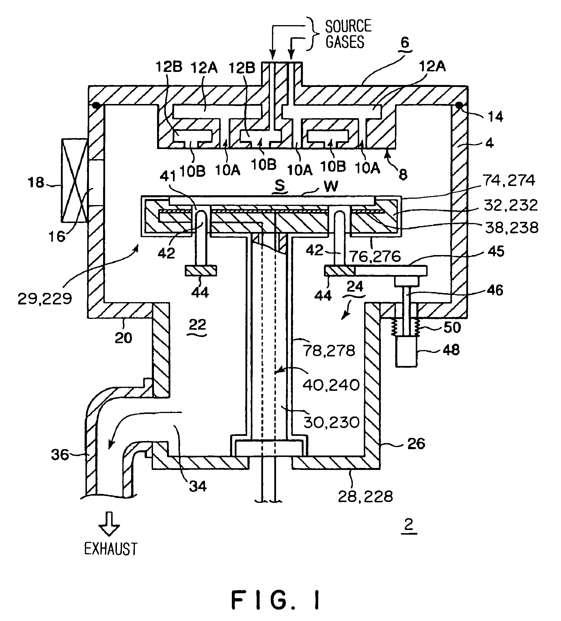
[0067]FIGS. 1 to 3 show a thermal processing system provided with a support table structure in a first embodiment according to the present invention.

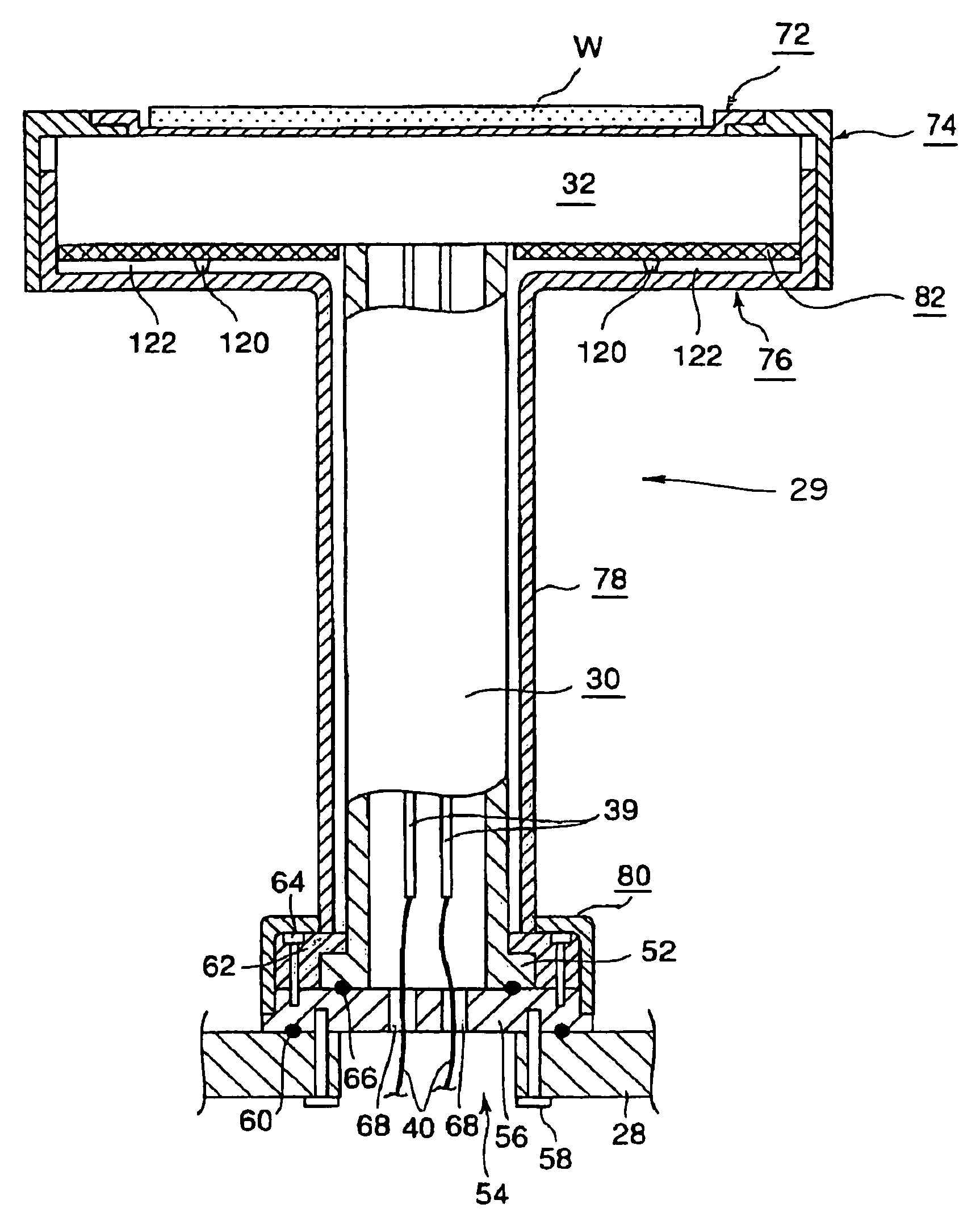
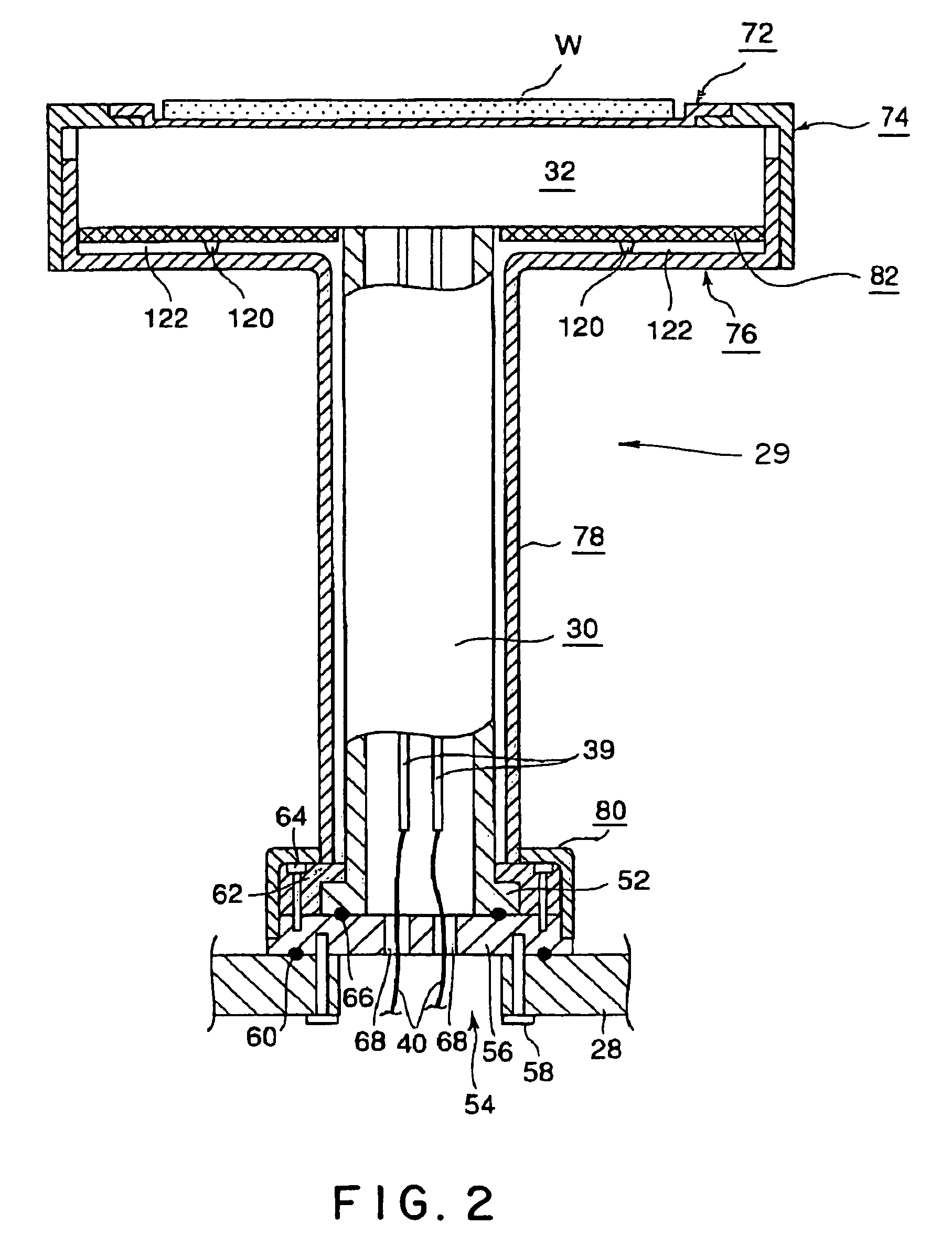
[0068]FIG. 1 is a schematic sectional view of a thermal processing system embodying the present invention provided with a support table structure embodying the present invention, FIG. 2 is a sectional view of a support table structure in a first embodiment according to the present invention and FIG. 3 is an exploded perspective view of a cover structure included in the support table structure shown in FIG. 2.

[0069]Referring to FIGS. 1 to 3, a thermal processing system 2 has a processing vessel 4 made of aluminum and defining, for example, a substantially cylindrical processing space S. The processing vessel 4 has a top wall provided with a shower head 6. Process gases, such as source gases, are supplied through the shower head 6 into the processing vessel 4. Gases are jetted through gas jetting holes formed in a gas jetting wall 8 inclu...

second embodiment

[0104]A support table structure 229 in a second embodiment according to the present invention will be described with reference to FIGS. 4 to 9. Referring to FIG. 4, the support table structure 229 includes a support table 232 and a support post 230. The support table 232 and the support post 230 are made of a highly heat-resistant, highly corrosion-resistant material, such as transparent quartz glass. The support table 232 and the support post 230 are covered with an upper surface covering member 272, a peripheral surface covering member 274, a lower surface covering member 276, a support post covering member 278, a lower end covering member 280 and an opaque back cover 282. As shown in FIG. 6, the support table 232 is a three-layer structure formed by superposing a top plate 300A, a middle plate 300B and a bottom plate 300C in that order and welding together the top plate 300A, the middle plate 300B and the bottom plate 300C. The thin upper surface covering member 272 made of an op...

third embodiment

[0143]In the foregoing embodiments, the support table 232 and the support post 230 are covered with the covering members. A support table structure 629 in a third embodiment according to the present invention shown in FIG. 13 is not provided with any covering members. As shown in FIG. 13, the support table structure 629 does not have any members corresponding to the peripheral surface covering member 274, the lower surface covering member 276, the support post covering member 278 and the lower end covering member 280 shown in FIG. 4. An opaque back cover 282 is disposed in contact with the lower surface of a support table 232. Even if unnecessary films are deposited in patches on the lower surface of the opaque back cover 282, the opaque back cover 282 protects the support table 232 from the detrimental thermal effect based on the unnecessary films. An upper surface covering member 272 is placed on the upper surface of the support table 232 to improve the uniformity of intrasurface ...


PUM

PropertyMeasurementUnit
thicknessaaaaaaaaaa
wall thicknessaaaaaaaaaa

Abstract

A thermal processing system has a processing vessel 4, a support post 30 stood on the bottom wall of the processing vessel 4, and a support table 32 internally provided with a heating means 38 and supported on the support post 30. A workpiece W is placed on the upper surface of the support table 32 and is subjected to a predetermined thermal process. The upper, the side and the lower surface of the support table 32 are covered with heat-resistant covering members 72, 74 and 76 to prevent the thermal diffusion of metal atoms causative of contamination from the support table 32. thus, various types of contamination, such as metal and organic contamination, can be prevented.

Description

TECHNICAL FIELD[0001]The present invention relates to a support table structure for supporting a workpiece, such as a semiconductor wafer, and a thermal processing system provided with the same.BACKGROUND ART[0002]A workpiece, such as a semiconductor wafer, is subject repeatedly to single-wafer processing processes, such as a film deposition process, an etching process, a thermal process, a modifying process and a crystallization process to build a desired semiconductor integrated circuit on the workpiece. Those processes use necessary process gases. For example, the film deposition process uses film forming gases, the modifying process uses ozone gas, the crystallization process uses an inert gas, such as N2 gas, and O2 gas. Those process gases are supplied into a processing vessel.[0003]For example, a single-wafer thermal processing system for processing a single wafer at a time by a heat treatment process places a support table internally provided with, for example, a resistance ...

Claims


Application Information

Patent Timeline
Patent Type & Authority Patents(United States)
IPC IPC(8): H05B3/28F27B5/14C23C16/458H01L21/00H01L21/687
CPCC23C16/4581H01L21/67103H01L21/68792H01L21/68785H01L21/68757H01L21/324
Inventor KAWASAKI, HIROOIWATA, TERUOAMIKURA, MANABU
Owner TOKYO ELECTRON LTD
Why Eureka
Try Eureka