
Composite membrane material for hydrogen separation and element for hydrogen separation using the same

a technology of hydrogen separation and composite membrane, which is applied in the direction of membranes, separation processes, physical/chemical process catalysts, etc., can solve the problems of troublesome maintenance of plants, high cost of plants, and purity of obtained hydrogen gas, so as to improve the efficiency of hydrogen separation treatment and prevent the influence of performance degradation. , the effect of high accuracy

Active Publication Date: 2010-01-28
NIPPON SEISEN CO LTD
View PDF10 Cites 4 Cited by
  • Summary
  • Abstract
  • Description
  • Claims
  • Application Information

AI Technical Summary

Benefits of technology

The present invention relates to a composite membrane material for hydrogen separation which can be used for high-purity hydrogen gas production. The membrane material is made of a hydrogen-permeable membrane supported by a porous support and is designed to have high adhesion strength between the membrane and the support. The membrane material can be used in a hydrogen separation process that requires low temperatures and low pressure, making it more energy efficient and cost-effective compared to conventional methods. The invention also provides an improved hydrogen separation membrane that can be used in a membrane reactor for on-site hydrogen generation.

Problems solved by technology

However, in this process using the PSA, the equilibrium reaction temperature is as high as about 800° C. Further, in addition to complexity and size increase of plant itself and increase in process steps and number of equipments, the plant cost is high and the maintenance of plant is troublesome.
Moreover, the purity of the obtained hydrogen gas is not satisfactory and, therefore, improvement of this process is desired also from the viewpoint of hydrogen gas purification efficiency, so the process has not sufficiently spread.

Method used


Image

  • Composite membrane material for hydrogen separation and element for hydrogen separation using the same
  • Composite membrane material for hydrogen separation and element for hydrogen separation using the same
  • Composite membrane material for hydrogen separation and element for hydrogen separation using the same

Examples


example 1

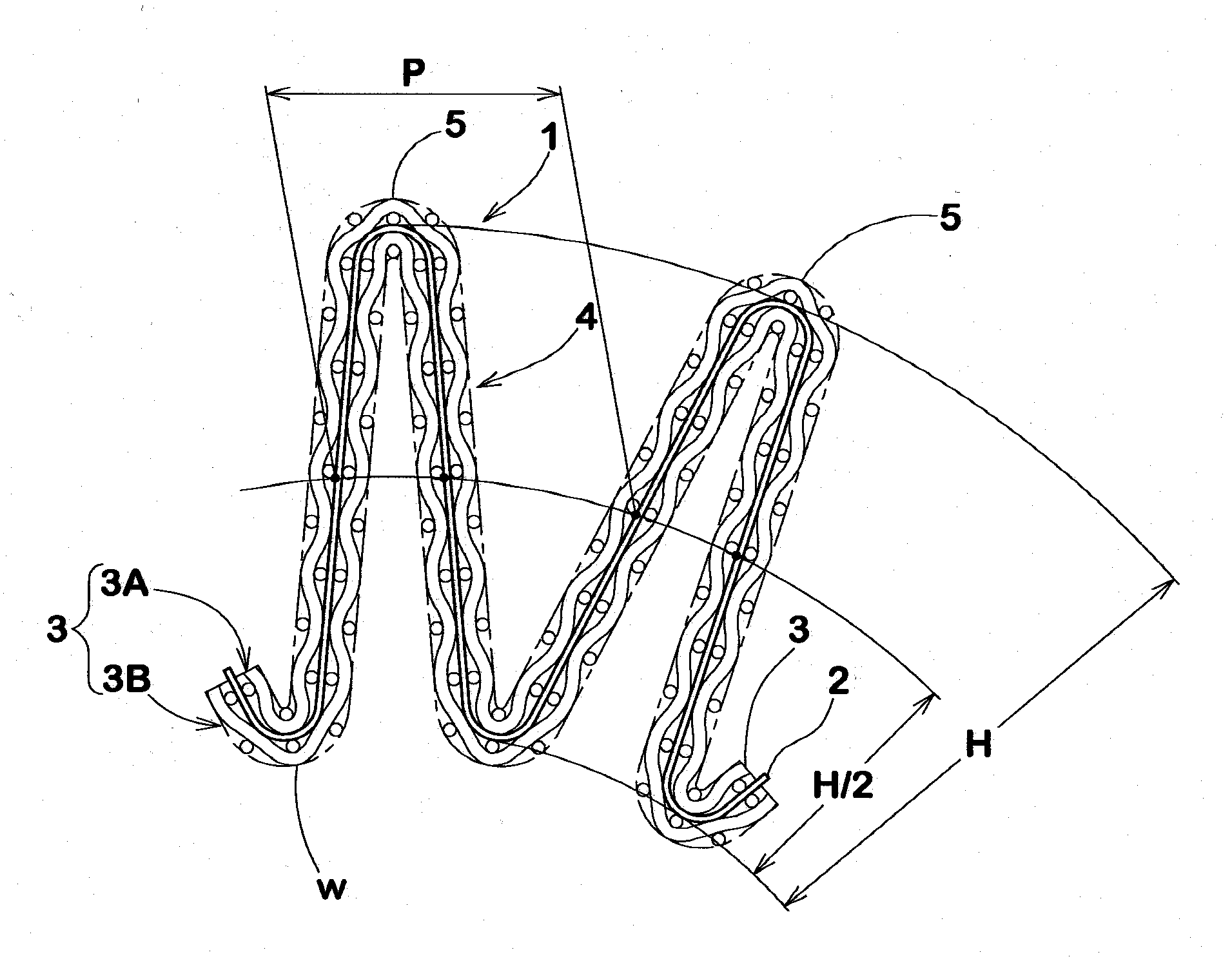
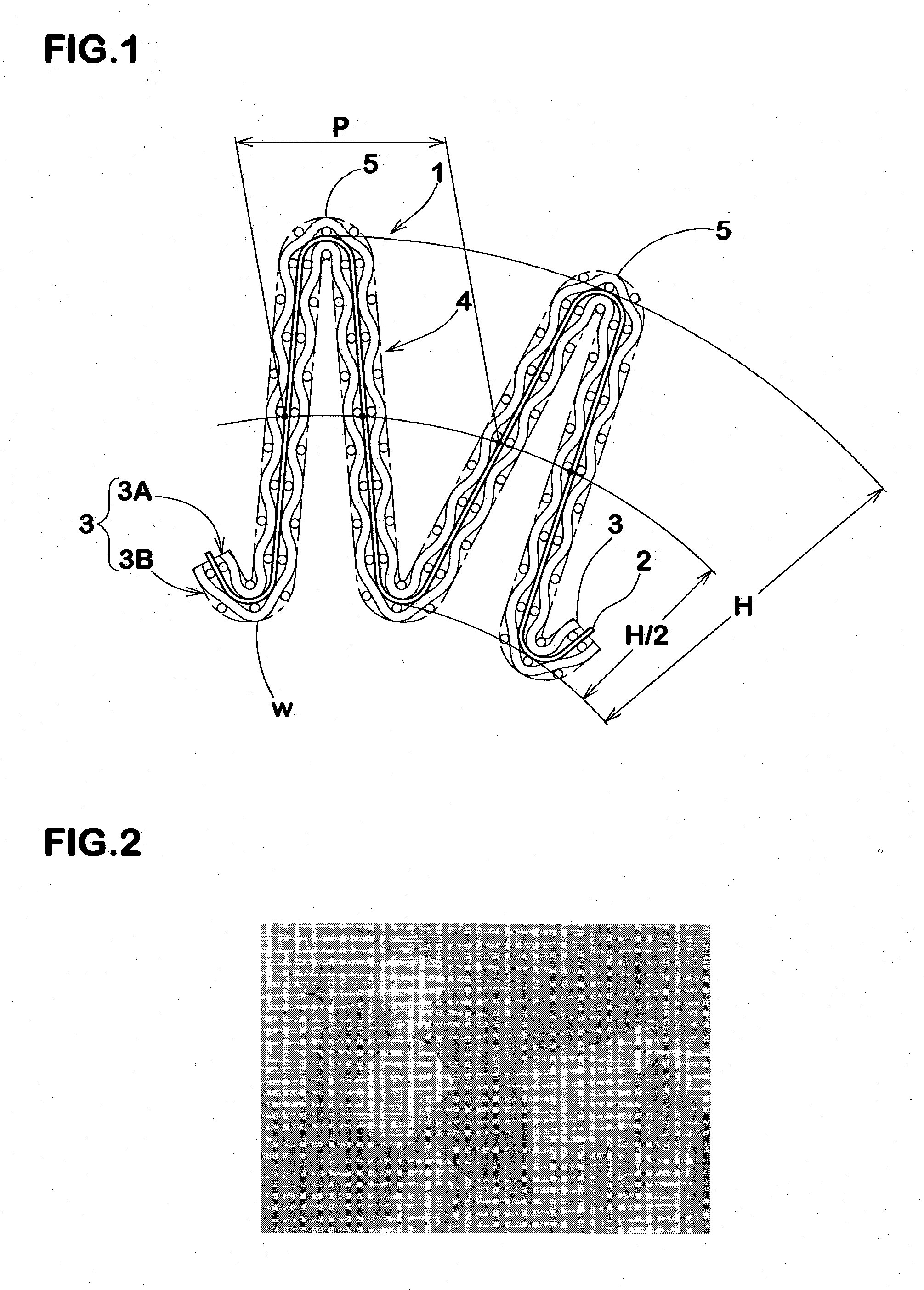
[0079]A Pd-25% Ag metal foil having a size of 100 mm width×1 m length was prepared by cold rolling to a thickness of 20 μm and heat treatment at 1,050° C. to give a hydrogen-permeable membrane. Shape-retention meshes (#100) made of a molybdenum wire having a diameter of 0.2 mm were superposed on the both surfaces of the membrane, and the resulting laminate is set up in a pleat forming machine. This three-layer laminate was pleated to form continuous pleats having a ridge height of 20 mm and a center pitch of 6.5 mm, thus providing a pleated composite membrane material. A Pd—Ag alloy plate which was purified by vacuum melting to a purity of 99.91% and processed by repeating rolling and heat treatment was used as a raw material of the above-mentioned Pd—Ag alloy.

[0080]In this state, the hydrogen-permeable membrane and the shape-retention meshes were in close contact with each other, although they were in a non-bonded state. Return such as spring back was scarcely observed and pleat sh...


PUM

PropertyMeasurementUnit
thicknessaaaaaaaaaa
melting pointaaaaaaaaaa
thicknessaaaaaaaaaa

Abstract

A composite membrane material characterized by comprising a hydrogen-permeable membrane which is selectively permeable to hydrogen and is formed by rolling to a thickness of 30 μm or less which is difficult for the membrane by itself to retain its shape, and a shape-retention mesh which is disposed on at least one side of the hydrogen-permeable membrane and is composed of a wire of a high-melting metal which does not cause thermal diffusion into the hydrogen-permeable membrane, wherein the hydrogen-permeable membrane and the shape-retention mesh are superposed and subjected to a pleat processing in a non-bonded state so that they are separable and the hydrogen-permeable membrane has a surface area increased at least 3 times per unit area. This material is used to constitute a hydrogen separation element.

Description

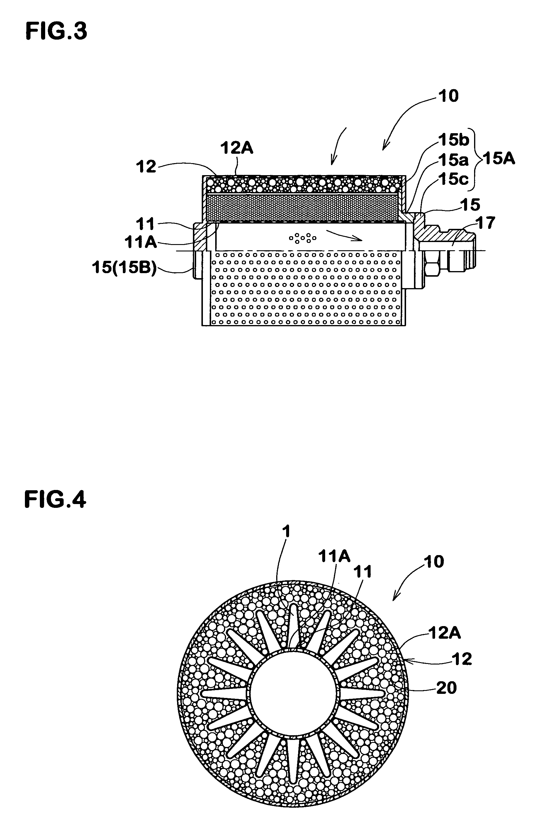
TECHNICAL FIELD[0001]The present invention relates to a composite membrane material for hydrogen separation which can be used for separation of high-purity hydrogen by selective permeation of hydrogen gas from a hydrogen-containing mixed gas, and an element for hydrogen separation using the same.BACKGROUND ART[0002]For production of hydrogen as an energy source for the next generation are known, for example, a process by electrolysis of water, and a process for obtaining hydrogen by steam reforming of various raw gases such as methanol, propane gas, liquefied natural gas and city gas. In particular, in the latter process, a mixed gas containing hydrogen gas is obtained by reforming and conversion of these gases. However, for utilizing the hydrogen gas as a fuel to generate electricity, it is required to separate a hydrogen gas having a high purity of 99.99% or more.[0003]When a natural gas is used as a raw gas, the following hydrogen separation process is used as shown in FIG. 8. Af...

Claims


Application Information

Patent Timeline
Patent Type & Authority Applications(United States)
IPC IPC(8): B01D53/22
CPCB01D53/22B01D63/12B01D63/14C01B2203/0405B01D2313/42C01B3/505B01D69/10C01B3/56B01D69/108B01D69/1213B01D63/067B01D71/022B01D53/228B01D2256/16B01D2325/22B01D2325/04
Inventor ISHIBE, HIDEOMITAGA, HIROYASU
Owner NIPPON SEISEN CO LTD
Learn More