Ignition operating mechanism for slide type lighters

a technology of operating mechanism and slide type, which is applied in the direction of lighting and heating apparatus, burners, combustion processes, etc., can solve the problems of not reaching the sufficient operation stroke of piezoelectric mechanisms, failing to give the operation stroke, etc., to reduce the burden on the operator's finger, and prevent careless ignition or ignition

Inactive Publication Date: 2003-08-21
TOKAI
View PDF13 Cites 9 Cited by
  • Summary
  • Abstract
  • Description
  • Claims
  • Application Information

AI Technical Summary

Benefits of technology

0012] As understood from the above description, there requires a 2-step operation of the operation member, thereby ensuring to prevent careless ignition or ignition by misuse or the like.
0013] And the 2-step ignition operation can be carried out in a course of a single movement of the operation member, thereby minimizing the burden to the operator's finger and maintaining good operability.
0014] Additionally, the 2-step operation gives a time from emission of the fuel gas to the ignition as compared to the conventional spark ignition only by the slide operation, thereby providing sufficient time delay for mixing the fuel gas with air inside the cap and enhancing ignition reliability.

Problems solved by technology

In this case, simple slide operation of the operation member fails to give the operation stroke sufficient to completely push the piezoelectric mechanism because the pushing portion disengages from the portion to be pushed of the piezoelectric mechanism at the end of the slide operation.
However, downward pushing of the operation member subsequent to the slide operation ensures that the operation member deforms and forces the portion to be pushed to be pushed down so that discharge voltage is generated for spark ignition.
In this case, since the simple sliding of the operation member restricts the downward movement of the portion to be pushed at the end of slide operation, thereby not reaching the sufficient operation stroke of the piezoelectric mechanism.

Method used


Image

  • Ignition operating mechanism for slide type lighters
  • Ignition operating mechanism for slide type lighters
  • Ignition operating mechanism for slide type lighters

Examples


first embodiment

[0025] (First Embodiment)

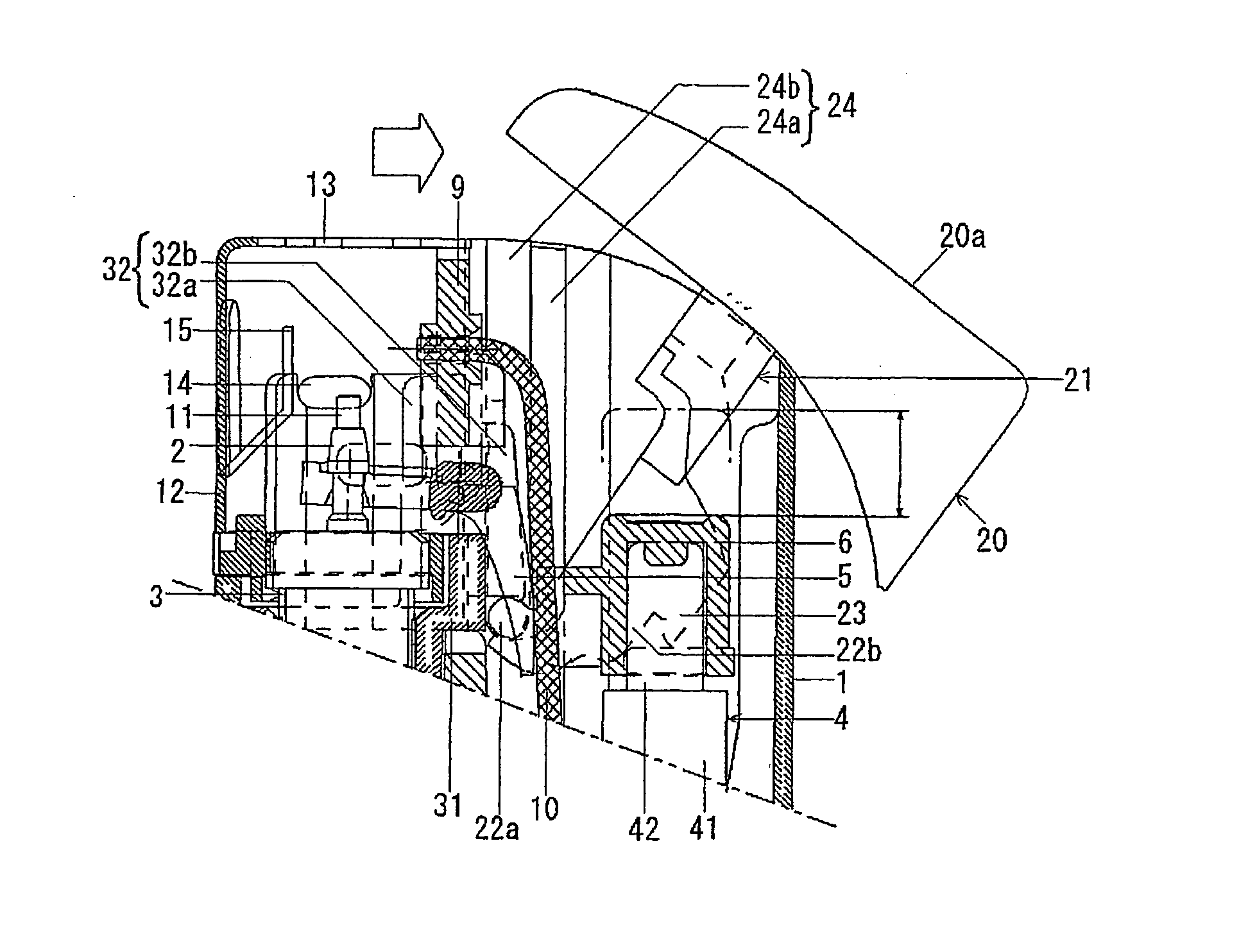
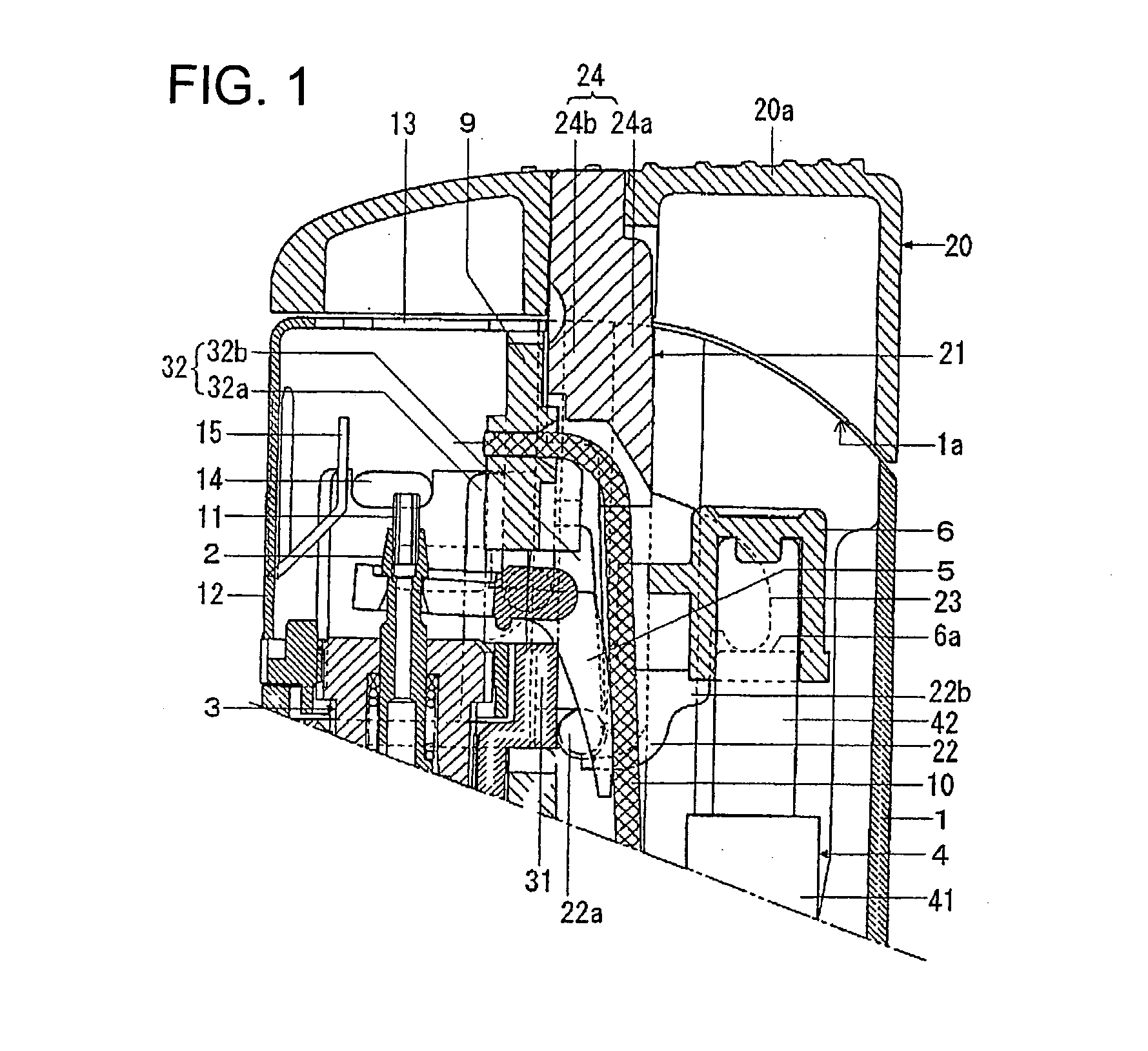
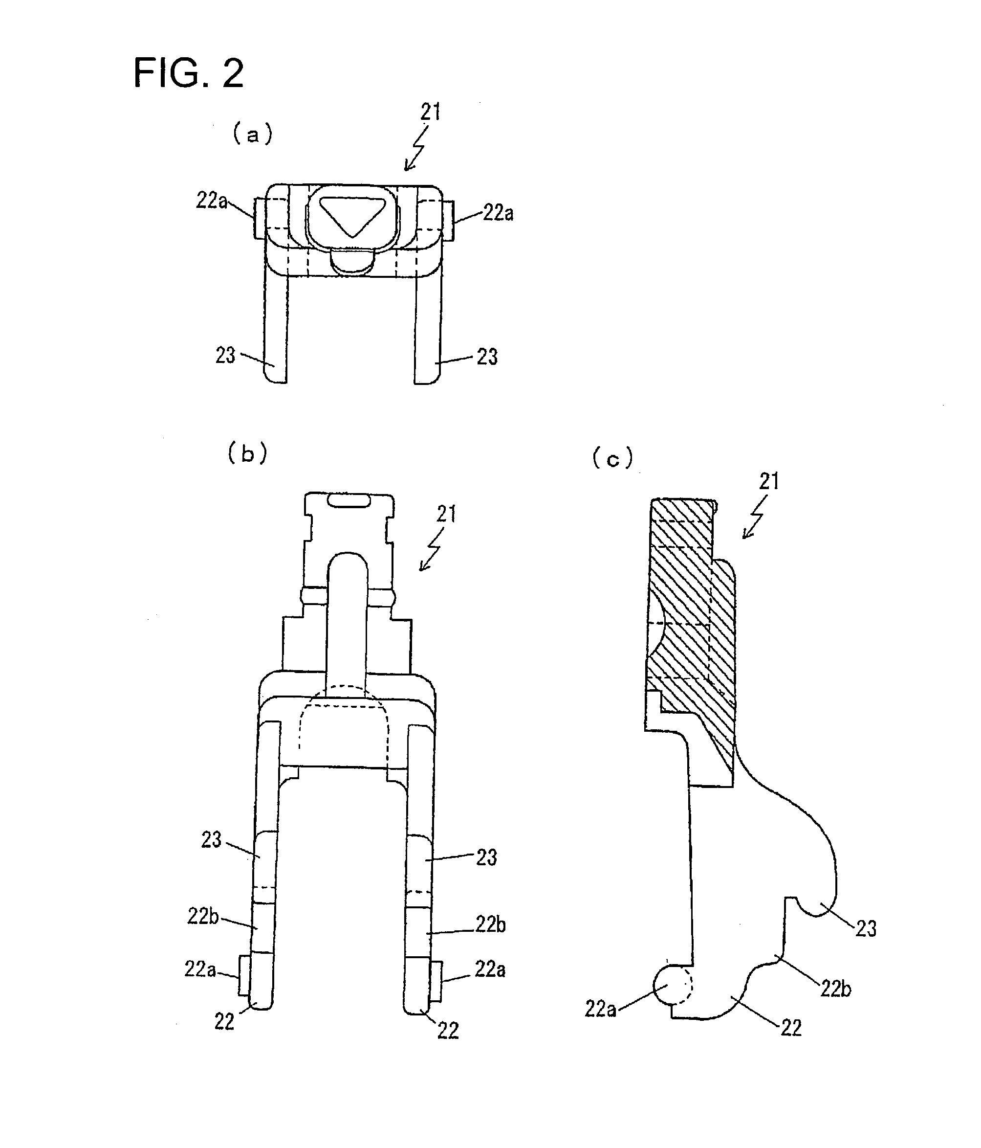
[0026] FIGS. 1-4 show a first embodiment of the present invention (the embodiment corresponding to claims 1 and 2). FIG. 1 is a longitudinal cross section view of the upper portion of the slide type lighter according to the first embodiment. FIG. 2 shows a lever member of an operating cap of the slide type lighter, wherein (a) is a plan view, (b) is a front view and (c) is a longitudinal cross section view. FIG. 3 is a cross section perspective view of the upper portion of a lighter main body of the slide operation type lighter. FIG. 4 shows the upper portion of the slide type lighter, wherein (a) is a longitudinal cross section view in the middle of ignition operation and (b) is a longitudinal cross section view at the time of ignition.

[0027] As shown in FIG. 1, the lighter comprises a lighter main body 1 constituting a tank for filling fuel gas therein. Disposed at one end of and inside the lighter main body 1 is an emission unit 3 having a nozzle 2 for em...

second embodiment

[0050] (Second Embodiment)

[0051] FIGS. 5 and 6 show a second embodiment of the present invention (the embodiment corresponding to claims 1 and 3). FIG. 5 is a longitudinal cross section view of the upper portion of the slide type lighter according to the second embodiment of the present invention. FIG. 6 is a longitudinal cross section view of the upper portion of the slide type lighter, wherein (a) is in the middle of ignition operation while (b) is at the time of ignition.

[0052] The lighter of the second embodiment has basically the same construction and function as the lighter of the present invention. Accordingly, the portions common to those of the first embodiment have the same reference numerals in the drawings and the following descriptions are focused mostly on special portions to this embodiment.

[0053] In this embodiment, it is adapted that the post portions 32b, 32b of the upper lid 31 are fitted into the engaging portions 24b, 24b of the grooves 24, 24 in the lighter mai...

third embodiment

[0056] (Third Embodiment)

[0057] FIGS. 7 and 8 show a third embodiment of the present invention (the embodiment corresponding to claims 1 and 4). FIG. 7 is a longitudinal cross section view of the upper portion of the slide type lighter according to the third embodiment. FIG. 8 shows a longitudinal cross section view of the upper portion of the slide type lighter, wherein (a) is in the middle of the ignition operation and (b) is in the ignition operation.

[0058] Again, the lighter in the third embodiment has basically the same construction and function as the lighter in the first embodiment. The portions common to those of the first embodiment have the same reference numerals and the following descriptions are focused mostly on the special matters to this embodiment.

[0059] In this embodiment, the lighter is assembled by fitting the post portions 32b, 32b of the upper lit 31 into the engaging portions 24b, 24b of the grooves 24, 24 in the lighter main body 1. The support portions of th...


PUM

PropertyMeasurementUnit
discharge voltageaaaaaaaaaa
timeaaaaaaaaaa
distanceaaaaaaaaaa

Abstract

An ignition operation mechanism for slide type lighters that is capable of preventing accidental ignition or ignition due to erroneous use or the like while maintaining good operability, wherein pivots 22a, 22a for an operating cap 20 are made substantially circular in cross section and so sized as to form a vertically movable clearance as they are locked to a support section in the lighter main body, the pivots 22a, 22a for the operating cap 20 are normally urged to be positioned in the upper region of the interior of a support section by the spring force of a return spring for a piezoelectric mechanism 4, the operating cap 20 is slid until a lever member 21 strikes the lighter main body 1 and no longer moves in the slide direction, from which state (a), the operating cap is pressed downward, whereby the pivots 22a, 22a move downward (b) within the support section, whereupon pressing levers 23, 23 reach the operation stroke that overcomes the piezoelectric mechanism 4, producing a discharge voltage to enable ignition.

Description

[0001] The present invention relates to an ignition operating mechanism for slide type lighters for spark igniting such lighters by sliding operation of an operation or actuation member.SUMMARY OF THE INVENTION[0002] Among ignition operating mechanisms for piezoelectric ignition type gas lighters, there is a kind of lighters constructed to generate discharge voltage by pushing the piezoelectric mechanism as a result of slide operation of a pivotally supported operating cap, thereby causing spark discharge at the end of a nozzle to ignite the gas emitting from the nozzle. Gas lighters provided with such slide type ignition mechanism are generally known as slide type (or rocking type) lighters.[0003] Incidentally, piezoelectric gas lighters require any type of safe guard to prevent accidental ignition by carelessly touching the ignition operating mechanism with a finger or the like or in case of children playing with such lighters. Conventional measures to prevent such accidental igni...

Claims


Application Information

Patent Timeline
Patent Type & Authority Applications(United States)
IPC IPC(8): F23Q2/28
CPCY10T29/49348F23Q2/287
Inventor SUZUKI, TAKAYUKIMOCHIZUKI, TETSUYA
Owner TOKAI
Why Eureka
Try Eureka