Method and apparatus for hermetically sealing openings of an explosion containment chamber

a technology of containment chamber and hermetically sealing, which is applied in the direction of lighting and heating equipment, nuclear engineering, combustion types, etc., can solve the problems of many extremely dangerous and toxic materials which can be destroyed, and the subsequent release of toxins can be extremely deadly to the human population

Inactive Publication Date: 2003-08-28
CH2M HILL DEMILITARIZATION
View PDF0 Cites 6 Cited by
  • Summary
  • Abstract
  • Description
  • Claims
  • Application Information

AI Technical Summary

Benefits of technology

0017] The present invention further incorporates a vacuum tube connection. The proximate end of the vacuum tube is connected to an orifice located approximately in the center of the airlock door and is connected to the explosion chamber's air handling device at its distal end. As such, subsequent to detonating an explosion, the air-handling device is started and th

Problems solved by technology

This type of weaponry is generally destroyed by detonating the weapon with a predetermined amount of explosive material.
As can be expected, there are many extremely dangerous and toxic materials which can be destroyed within the explosion containment and suppression chamber.
It is thus imperative that these dangerous toxins are properly contained and not allowed to enter the atmosphere throughout the entire destruction process, whereas subsequent toxin release can be extremely deadly to the human population.
As stated previously, the initial destruction of the weapon by explosion vaporizes substantially all of the toxic

Method used


Image

  • Method and apparatus for hermetically sealing openings of an explosion containment chamber
  • Method and apparatus for hermetically sealing openings of an explosion containment chamber

Examples


Embodiment Construction

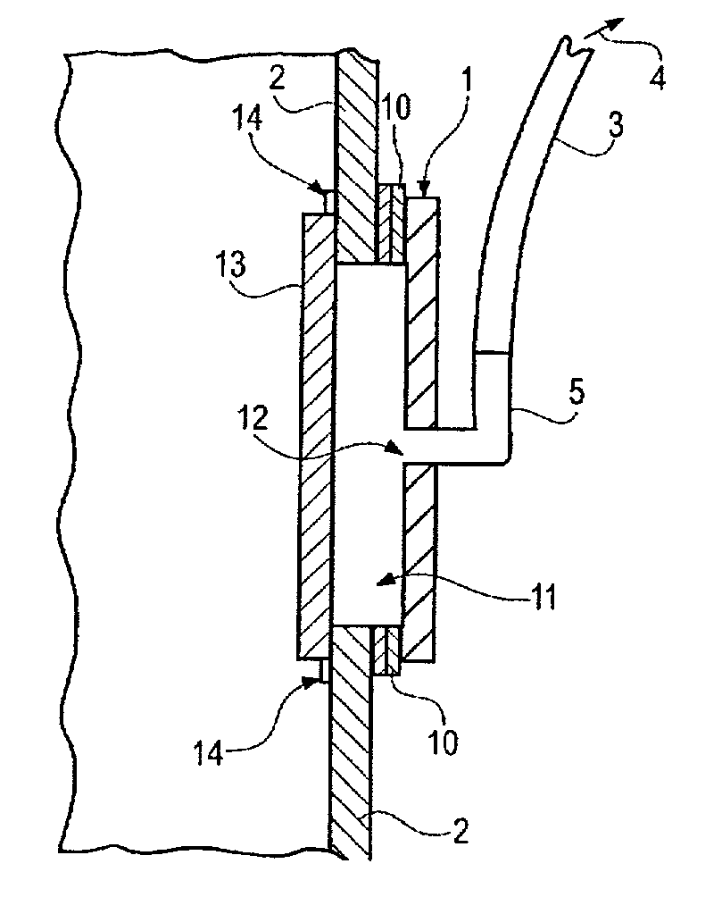
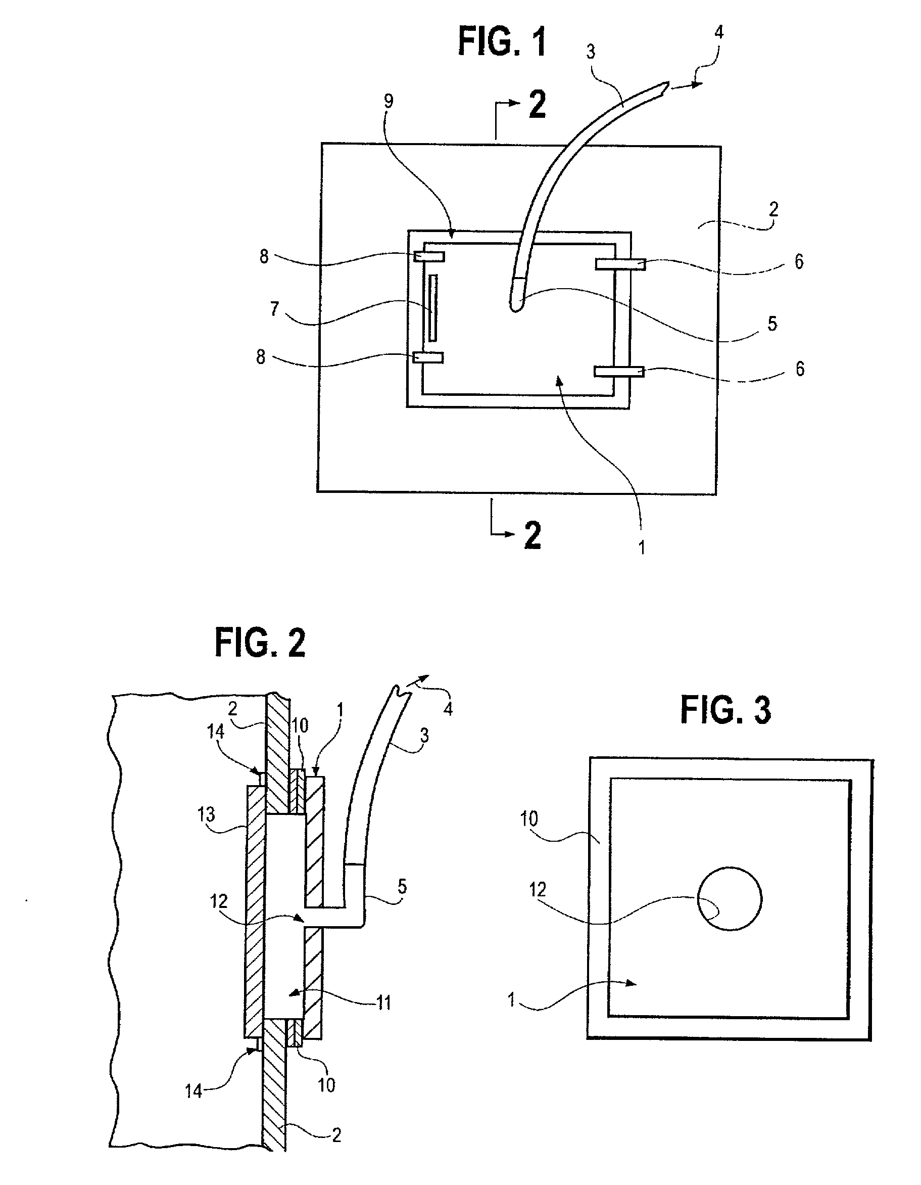
[0022] The preferred embodiment of the present invention is best described as a negative pressure airlock access door to an explosion containment and suppression chamber. The present invention is intended to be utilized with an explosion suppression chamber as disclosed in my U.S. Pat. Nos. 6,173,662, 5,884,569, and Re. 36,912. It is to be understood, of course, that the present invention can be utilized with differing configurations and on different types and designs of explosion suppression chambers, or other devices which require such an airlock design, while still achieving its objectives and goals. By providing a self-contained cavity between the explosion suppression chamber primary door and the environment, the present invention has the ability to controllably ensure that there are no toxins released into the environment.

[0023] Referring to FIGS. 1, 2 and 3, the present invention airlock door 1 is preferably pivotally connected to the outside face of the explosion chamber 2 w...


PUM


Abstract

A method and apparatus to hermetically seal openings in an explosion suppression chamber. The present invention utilizes an air lock device to ensure that, in the event toxins are released from the primary explosion chamber opening closing means, the toxins are properly handled and are not inadvertently released into the atmosphere. The preferred embodiment of the present invention uses negative pressure to vacuum the entrained air within the airlock cavity subsequent to an explosion. An alternate embodiment of the present invention uses positive pressure within the air lock cavity to force air through integral filter membranes.

Description

[0001] This application is related to my co-pending application Ser. No. 09 / 457,976, filed Dec. 9, 1999, now issued U.S. Patent No. which is a continuation-in-part of my application Ser. No. 09 / 191,045, filed on Nov. 12, 1998, now issued U.S. Pat. No. 6,173,662. patent application Ser. No. 09 / 191,045 is also a continuation-in-part of my application Ser. No. 08 / 823,223 filed Mar. 24, 1997, now issued U.S. Pat. No. 5,884,569. The latter application is a continuation-in-part of my parent application Ser. No. 08 / 578,200, filed Dec. 29, 1995, now issued U.S. Pat. No. 5,613,453 which has since been reissued with Re. 36,912 on Oct. 17, 2000. This patent application is commonly assigned as the patents and applications stated above and incorporates herein all of the same by reference.BACKGROUND OF INVENTION[0002] The present invention relates generally to a method and apparatus for containing, controlling and suppressing the detonation and destruction of explosives and resultant toxic materi...

Claims


Application Information

Patent Timeline
IPC IPC(8): F23G7/00F23M7/00F23M11/02F42B33/06F42D5/04
CPCF23G7/003F23G2209/16F42D5/04F23M11/02F42B33/067F23M7/00
Inventor DONOVAN, JOHN
Owner CH2M HILL DEMILITARIZATION
Why Eureka
Try Eureka