Method for vibrational impact on a pipe string in a borehole and devices for carrying out said method

a vibrational impact and pipe string technology, applied in the field of well construction, can solve the problems of increasing hydraulic power loss, affecting the stability of the knocker operation, and complex vibration generator design, and the need for an independent power supply

Inactive Publication Date: 2003-09-11
BIP TECH
View PDF6 Cites 7 Cited by
  • Summary
  • Abstract
  • Description
  • Claims
  • Application Information

AI Technical Summary

Problems solved by technology

The support (stopper of axial motion) made in the form of a grid adds surplus hydraulic resistance and induces vortexes in the fluid flow: the first results in additional losses of hydraulic power, the second affects stability of the knocker operation.
complexity of the vibrations generator design and a need in autonomous power supply;

Method used


Image

  • Method for vibrational impact on a pipe string in a borehole and devices for carrying out said method
  • Method for vibrational impact on a pipe string in a borehole and devices for carrying out said method
  • Method for vibrational impact on a pipe string in a borehole and devices for carrying out said method

Examples


Embodiment Construction

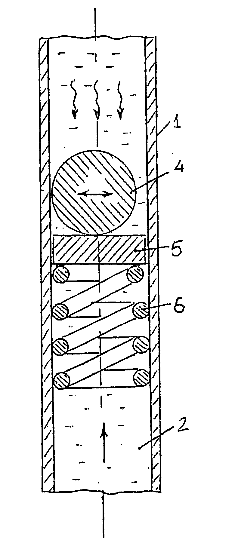
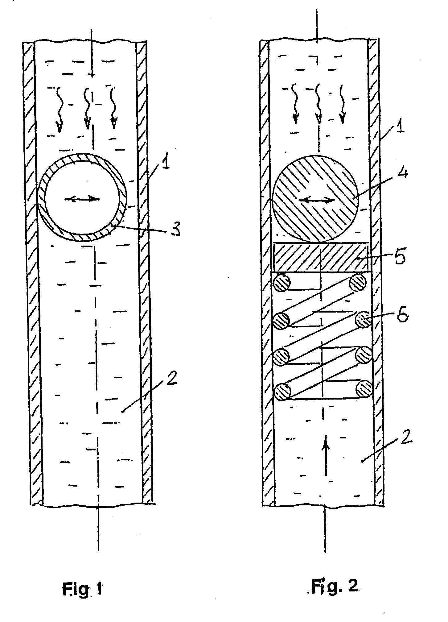
[0015] The proposed method of vibrational action on a string of tubes in a well comprises placement in the tubing string of an autonomous mechanism of vibrational action, pumping into the tubing string of a working fluid and transporting with it of the mechanism of vibrational action and simulataneous exciting by it of transverse oscillations of tubes in the string, where direction of transportation of the mechanism of vibrational action, frequency and amplitude of the tubes oscillations, and duration of the treatment within particular depth interval in the string of pipes are controlled by the working fluid pumping rate. Before placement of the mechanism of vibrational action into string of pipes a reference washing liquid pumping rate shall be firstly determined at which the transportation speed of the mechanism of vibrational action is equal to zero. The direction of transportation of mechanism of vibrational action is set in respect of this reference pumping rate, i.e. at higher...


PUM


Abstract

The invention relates to well construction and is directed at an oscillation excitation in a pipe string. According to the inventive method, an operating fluid is circulated in the pipe string. An autonomous mechanism for vibrational impact embodied in the form of an element, for instance a hollow ball having a rigid envelop and filled with gas, possessing a positive floatability, covering from 0.85 to 0.95 of a cross-sectional flow area of the pipe string and having an unrestricted degree of freedom. In the second variant, the inventive device comprises a ball support embodied in the form of a transverse beam or a crossbar rigidly connected to a spiral cylindrical spring arranged inside a tube under the ball with the aid of an easy-push fit. The spring force is selected with respect to a calculated axleload dependence on the mass of the ball and on flow strength with a basic flow rate of the operating fluid. A lateral oscillation is actuated simultaneously with a displacement of the mechanism for vibrational impact inside the pipe string. A direction of displacement of the mechanism for vibrational impact, verboten frequency and amplitude, and a time of action of the vibrational impact in a determined part of the pipe string are fixed with respect to the flow rate of the operating fluid. The speed of the displacement of the mechanism for vibrational impact is fixed with respect to the basic flow rate which is defined at zero speed. When the flow rate of the operating fluid exceeds the basic flow rate, the mechanism for vibrational impact is displaced towards the bottom of the well and when flow rate of the operating fluid decreases with respect to the basic flow rate, the mechanism for vibrational impact is displaced towards the well cellar. The invention reduces a friction force during displacement inside the well, precludes sticking and performs vibration impact on the fluid medium filling the well.

Description

FIELD OF USE[0001] This invention relates to construction of wells and is intended to produce vibrations in the string of tubes to reduce friction drag when it moves in the borehole, to free a stuck pipe and also to provide vibrational action on liquids that are filling the well.PRIOR ART[0002] A method is known to excite elastic oscillations in a well and a device therefor [USSR Certificate of Authorship no. 953183, 16.09.1980]. It comprises a moving element in the form of a ball that is placed into a string of tubes in a well, which ball transversely oscillates when pumping a liquid and due to this it hits the wall of the said tubes and thus transfers the oscillations to the string of pipes. The axial motion of the ball is limited by a support that is rigidly fixed at some location inside the tubing string.[0003] These method and device can be considered as a prior art analog to the proposed invention. One can refer to the following general shortcomings of this analog:[0004] Actio...

Claims


Application Information

Patent Timeline
Patent Type & Authority Applications(United States)
IPC IPC(8): E21B28/00E21B31/00
CPCE21B31/005E21B28/00
Inventor IVANNIKOV, VLADIMIR IVANNOVICHIVANNIKOV, IVAN VLADIMIROVICH
Owner BIP TECH
Why Eureka
Try Eureka