Fuel injection valve for internal combustion engines

a technology for internal combustion engines and fuel injection valves, which is applied in the direction of fuel injection apparatus, spraying apparatus, feeding system, etc., can solve the problems of difficult control of valve members, difficult metering and precise determination of injection instant, and severe mechanical stresses

Inactive Publication Date: 2003-09-11
ROBERT BOSCH GMBH
View PDF5 Cites 4 Cited by
  • Summary
  • Abstract
  • Description
  • Claims
  • Application Information

AI Technical Summary

Problems solved by technology

Because of these very fast closing events, which elapse within only a few milliseconds, pressure fluctuations in the high-pressure region of the fuel injection valve occur both upon the motion of the valve member and upon switching of the control valve; on the one hand, they cause severe mechanical stresses on the housing, and on the other, they have the effect that the subsequent injection

Method used


Image

  • Fuel injection valve for internal combustion engines
  • Fuel injection valve for internal combustion engines
  • Fuel injection valve for internal combustion engines

Examples


Embodiment Construction

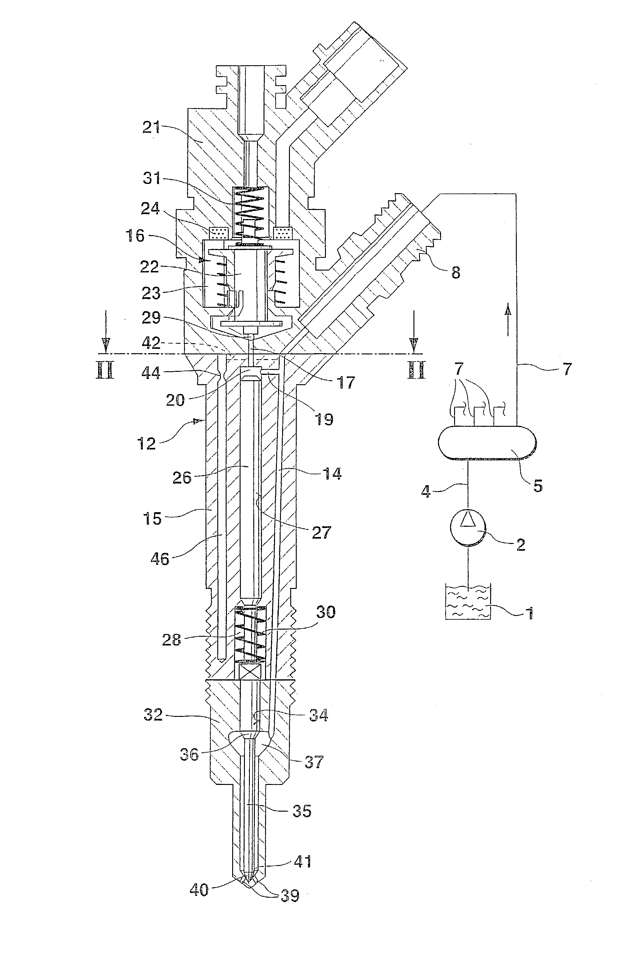
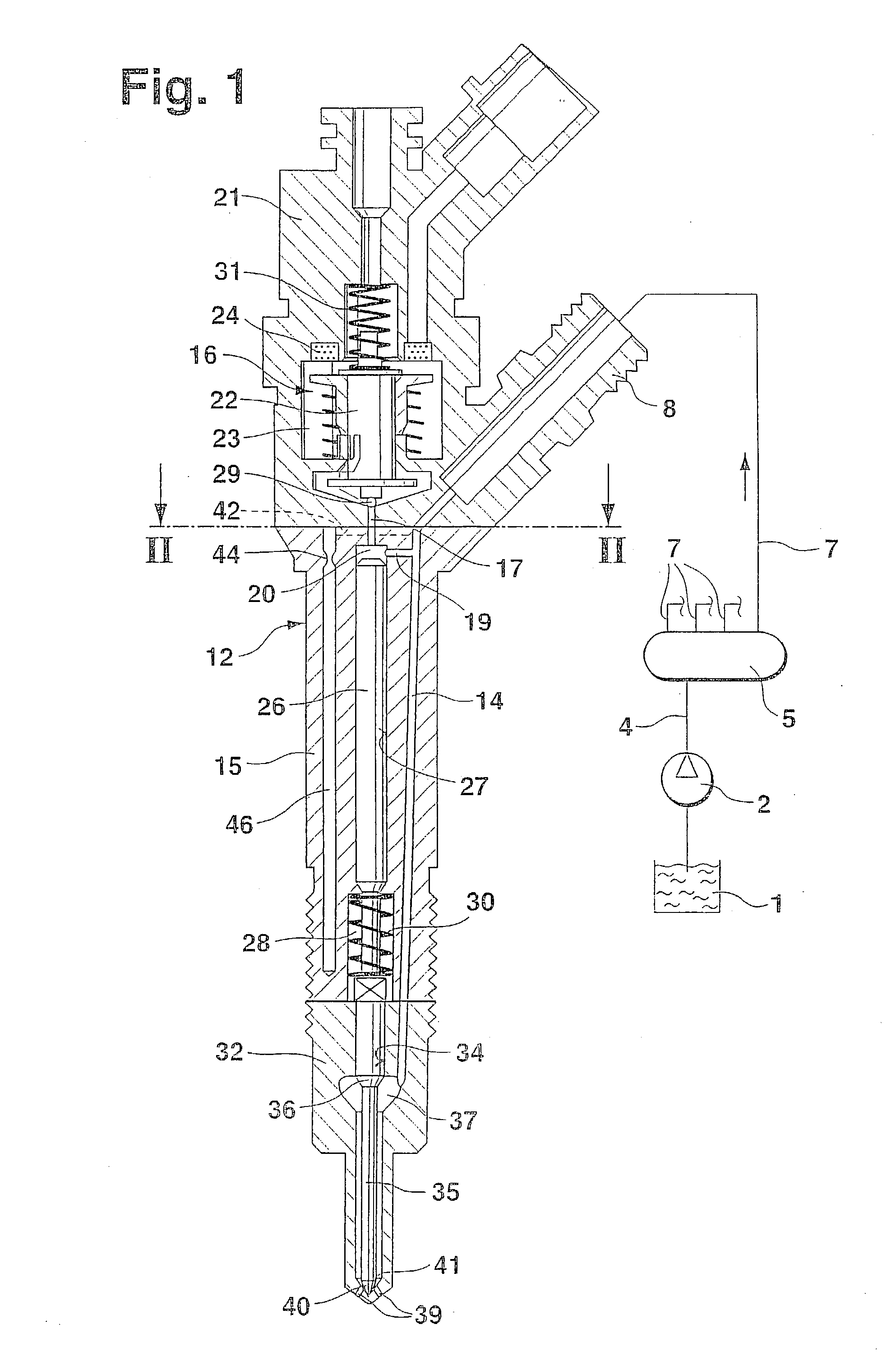
[0011] In FIG. 1, a longitudinal section through a fuel injection valve of the invention is shown, along with the schematically shown high-pressure fuel supply system. The fuel injection valve has a housing 12, which includes a valve holding body 15, a valve body 32, and a control valve body 21. Toward the combustion chamber, the valve body 32 is disposed in the engine, and the combustion chamber adjoins it, on the side remote from the valve holding body 15. The valve body 32 and the valve holding body 15 are braced against one another by means of a lock nut, not shown in the drawing for the sake of simplicity. The control valve body 21 is disposed on the side of the valve holding body 15 remote from the combustion chamber, and both bodies rest on the end faces facing one another. The control valve body 21 is braced against the valve holding body 15 by a device not shown in the drawing, so that a sealing communication between the fuel conduits extending in both bodies is possible.

[0...


PUM


Abstract

A fuel injection valve for internal combustion engines, having a housing (12) in which a pistonlike valve member (35) is disposed longitudinally displaceably in a bore (34) and by a longitudinal motion in an opening direction, with its end toward the combustion chamber, causes at least one injection opening (39) to communicate with a pressure chamber (37) embodied in the housing (12). An inlet conduit (14) is embodied in the housing (12) and discharges into the pressure chamber (37), and by way of it the pressure chamber (37) can be filled with fuel at high pressure. A fuel-filled control chamber (20) is also embodied in the housing (12); the pressure in the control chamber (20) at least indirectly exerts a force acting in the closing direction on the valve member (35). The control chamber (20) communicates with the inlet conduit (14) and can be made to communicate via a control valve (16) with a leak fuel chamber (23), in which a markedly lower pressure prevails than in the inlet conduit (14). In the housing (12), a damping chamber (46) is embodied, which communicates with the inlet conduit (14) via a throttle (44).

Description

PRIOR ART[0001] The invention is based on a fuel injection valve for internal combustion engines as defined by the preamble to claim 1. Such fuel injection valves are known from the prior art in various versions. For instance, in German Patent Disclosure DE 196 50 865 A1, a fuel injection valve is described that communicates constantly with a common rail in which fuel at high pressure is furnished. The fuel injection valve has a housing in which a valve member is disposed longitudinally displaceably in a bore; by its longitudinal motion, the valve member controls the opening of at least one injection opening, through which fuel from a pressure chamber surrounding the valve member is injected into the combustion chamber of the engine. The pressure chamber here communicates constantly with the common rail, via an inlet conduit extending in the housing of the fuel injection valve, and the fuel in the pressure chamber acts in the opening direction on a pressure face embodied on the valv...

Claims


Application Information

Patent Timeline
IPC IPC(8): F02M47/00F02M47/02F02M55/04F02M61/10F02M61/16F02M63/00
CPCF02M47/027F02M2200/315F02M55/04
Inventor EGLER, WALTERBOEHLAND, PETERKANNE, SEBASTIAN
Owner ROBERT BOSCH GMBH
Why Eureka
Try Eureka