Piezo actuator

a technology of actuators and actuators, applied in the direction of valve operating means/release devices, generators/motors, machines/engines, etc., can solve the problem of affecting the heat dissipation of air gaps to the valve housing, and the difficulty of valve housing dissipation

Inactive Publication Date: 2003-09-11
ROBERT BOSCH GMBH
View PDF9 Cites 13 Cited by
  • Summary
  • Abstract
  • Description
  • Claims
  • Application Information

AI Technical Summary

Problems solved by technology

The result is the disadvantage that the dissipation of heat through the air gap to the valve housing is made more difficult.

Method used


Image

  • Piezo actuator
  • Piezo actuator
  • Piezo actuator

Examples


Embodiment Construction

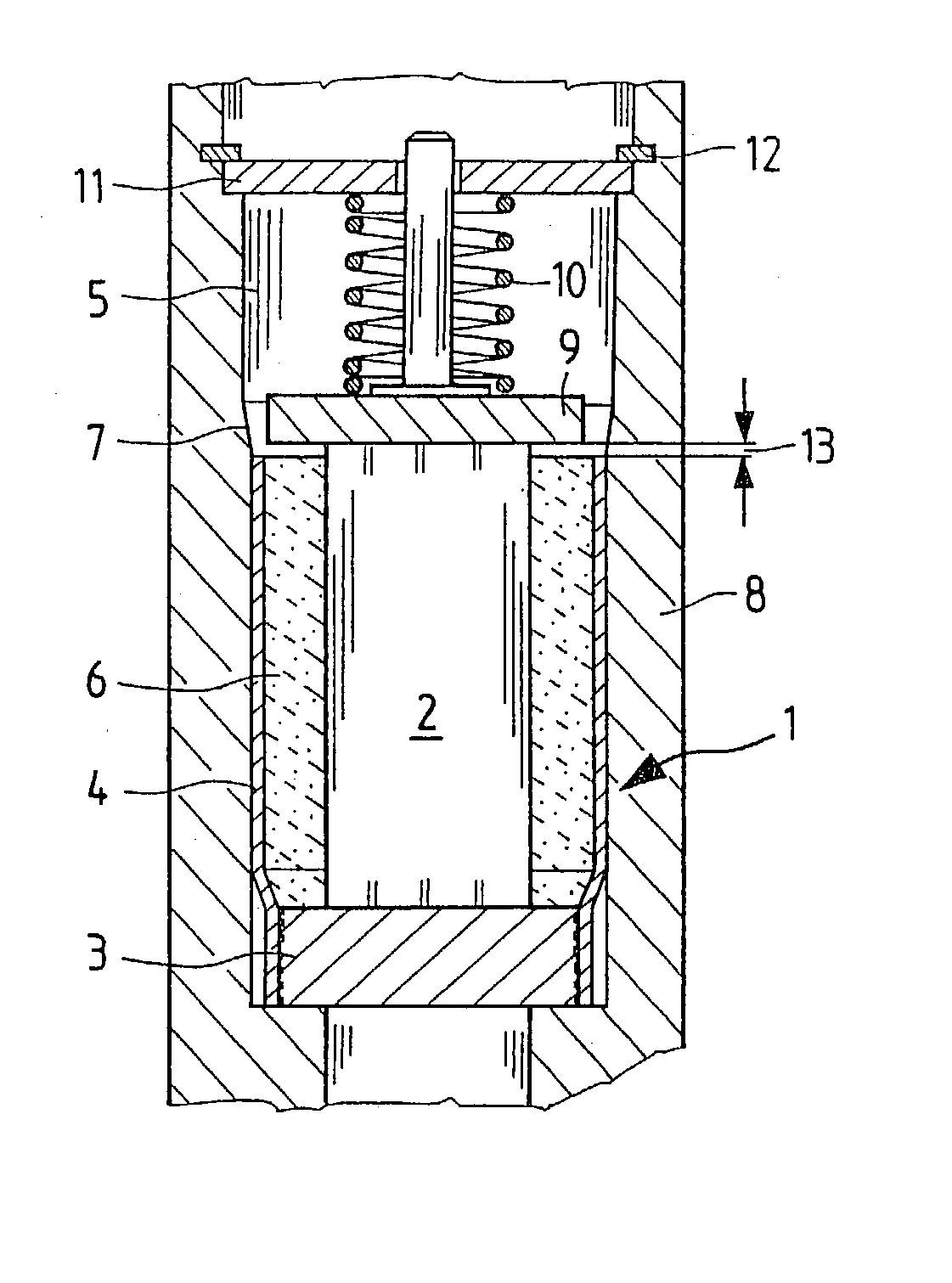
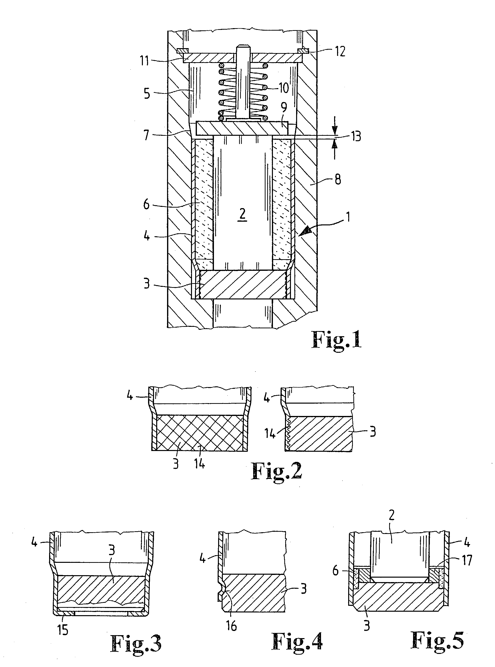
[0022] In FIG. 1, a piezoelectric actuator 1 is shown in the form of a piezoelectric multilayer actuator, which has a piezoelectric element 2 that in a manner known per se is constructed from piezoelectric sheets of a quartz material with a suitable crystalline structure, so that by using the so-called piezoelectric effect, when an external electrical voltage is applied to electrodes, not shown here, a mechanical reaction of the piezoelectric actuator 1 ensues, in the form of an axial motion.

[0023] On its fixed end, the piezoelectric actuator 1 is centered and solidly joined to a foot part 3 of steel or ceramic. On the foot part 3, a deformable and highly heat-conductive sleeve is put in place and joined to the foot part 3, for instance by welding. The sleeve 4 has a lesser diameter in the region of the foot part 3, since the sleeve 4, in the process of being press-fitted into a retaining bore 5, is unable to yield radially in this region because of the foot part 3. The sleeve 4 is ...


PUM


Abstract

A piezoelectric actuator (1) is proposed, in which a piezoelectric element (2) is present for subjecting an actuating element to a tensile or compressive stress. A sleeve (4; 20) is secured to a foot part (3), to which the piezoelectric element (2) is secured and by way of which the piezoelectric element (2) is kept centered in a housing (8) under mechanical prestressing, and this sleeve surrounds the piezoelectric element (2) in such a way as to stabilize it mechanically, at least in partial regions that are electrically insulated from the piezoelectric element. Between the sleeve (4; 20) and the piezoelectric element (2), a heat-conducting elastomer (6) is placed, and the sleeve (4; 20) comprises a heat-conducting material that is deformable within predetermined limits.

Description

PRIOR ART[0001] The invention relates to a piezoelectric actuator, for instance for actuating a mechanical component such as a valve or the like, as generically defined by the characteristics of the preamble to the main claim.[0002] It is generally known that by using the so-called piezoelectric effect, a piezoelectric element can be constructed from a material having a suitable crystalline structure. When an external electrical voltage is applied, a mechanical reaction of the piezoelectric element ensues, which as a function of the crystalline structure and the regions of contact with the electrical voltage exerts a pressure or tension in a predeterminable direction.[0003] From German Patent Disclosure DE 196 50 900, for instance, a piezoelectric actuator is known which is suitable particularly for actuating control valves or injection valves in motor vehicles. To that end, it comprises layers, stacked on one another in the manner of a laminate, of piezoelectric material with metal...

Claims


Application Information

Patent Timeline
Patent Type & Authority Applications(United States)
IPC IPC(8): F02M63/00F16K31/02H01L41/053H01L41/083H02N2/04
CPCF02M2200/21H01L41/0536H01L41/083F02M2200/26H10N30/886H10N30/50
Inventor HEINZ, RUDOLFHEDRICH, ALEXANDERBOECKING, FRIEDRICH
Owner ROBERT BOSCH GMBH
Why Eureka
Try Eureka