Air filter system for a free-standing air blowing fan

Inactive Publication Date: 2003-10-09
BOULVA PAUL
View PDF13 Cites 22 Cited by
  • Summary
  • Abstract
  • Description
  • Claims
  • Application Information

AI Technical Summary

Benefits of technology

0006] Another feature of the present invention is to provide a filter system for a free-standing air blowing fan and wherein the system comprises a support hub having a filter retention means in a rear portion thereof and a projecting air shield in a front edge thereof whereby to effectively clean air which passes through the fan blades from the filter at the rear of the hub while at the same time maintaining the fan blades and the cage substantially clean requiring less frequent maintenance than known prior art air blowing fan filtering systems of the type aforementioned. The filter support hub may also be an integrated part of the cage.
0007] Another feature of the present invention is to provide a filter system for a free-standing air blowing fan and wherein the system provides increased safety and is effective in removing dust, pollen, nicotine or cigarette smoke, microfibers and other pollutants from the air, thus improving the air quality in a room in which the fan is operating.
0008] Another feature of the present invention is to provide a filter system for a free-standing air blowing fan which is aesthetically pleasing in design and easy to service.
0009] Another feature of the present invention is to provide a filter system for a free-standing air blowing fan which is economical and which can serve as an effective, quiet operating, air filter thus eliminating the cost of purchasing an expensive air filtering system to substantially effect the same air cleansing. The air cleaning fan also consumes less energy and can be used on a contin

Problems solved by technology

A disadvantage of such filter is that when the fan is in operation, air is drawn not only through the filter but also from about the outer periphery of the cage.
A disadvantage of this is that the air which exits the front of the fan is not totally cleaned and still contains impurities.
Another disadvantage is that these impurities soil the fan blades as well as the peripheral front portion of the cage thus requiring the blades and the cage to be dismantled and cleaned from time to time.
Of course, as the filter becomes dirty, there is more and more air entering the area of the fan from about the periphery of the cage and accordingly as time goes by, most of the air will not be filtered.
A still further disadvantage of such filter arrangement is that the filter is totally exposed and usually placed in areas accessible to children.
Furthermore, such a filter arrangement is difficult to install and is visually not aesthetically pleasing to the fan structure.
However, these designs do not describe where the front edge of the cup-shaped filter terminates

Method used


Image

  • Air filter system for a free-standing air blowing fan
  • Air filter system for a free-standing air blowing fan
  • Air filter system for a free-standing air blowing fan

Examples


Example

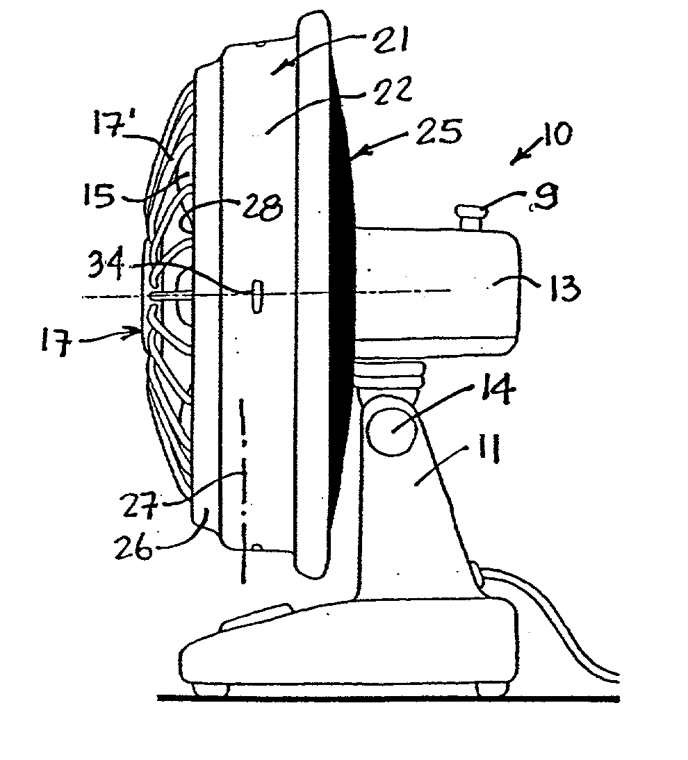
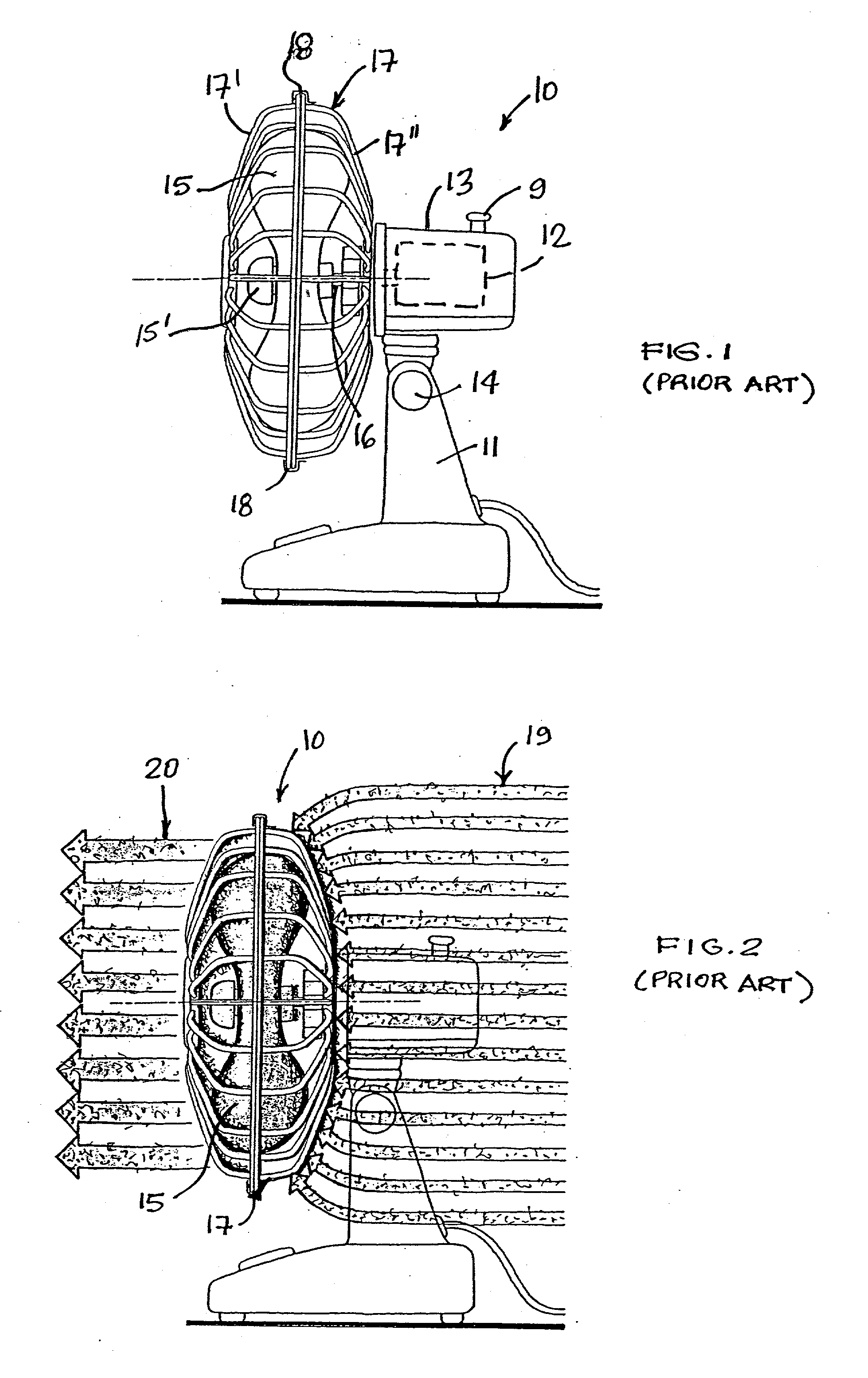
[0029] Referring now to the drawings, and more particularly to FIG. 1, there is shown generally at 10 a free-standing air blowing fan as is well known in the prior art. It consists of a support stand 11 for supporting a motor 12 housed in a motor housing 13. The motor housing 13 may be rigidly secured to the stand 11 or hingedly secured on a hinge adjustable by an adjustment knob 14 to set the vertical angle of the fan. The horizontal oscillating function of the fan is set by the control knob 9. Fan blades 15 are removably secured to a motor driven shaft 16 and are attached to the shaft 16 with a mounting nut 15' and rotate thereon. A cage 17 is secured to the front of the motor housing 13 and is usually constructed in two sections whereby the front section 17' can be detached from the fixed rear removably secured section 17" for cleaning the fan blades and cage. These sections are usually interconnected by clips 18.

[0030] The main purpose of these prior art fans is to displace air ...


PUM

PropertyMeasurementUnit
Pressureaaaaaaaaaa
Diameteraaaaaaaaaa
Flexibilityaaaaaaaaaa

Abstract

A filter system for a free-standing air blowing fan having a support stand, motor driven fan blades and a cage about at least portions of the blades, is described. The filter system comprises a filter support hub defined by a solid circumferential wall. The filter support hub is secured about or forms part of the cage. The hub is also provided with filter retention attachments rearwardly thereof for removable securement of a flat annular disc-shaped air filter behind the fan blades and cage. The filter support hub has a projecting air shield front edge projecting forwardly of a central planar axis of the fan blades of the fan to prevent ingress air flow from a front opened end of the filter support hub when the fan is operating. All the ambient air is accordingly drawn from the back through the filter.

Description

[0001] The present invention relates to a filter system which is part of or is attachable to a free-standing air blowing fan of the type which is mounted on a stand and wherein the fan blades are motor driven. The fan blades are protected by a cage secured thereabout and the fan blades and their cage are often displaced by a motor coupling whereby to oscillate the fan and to ventilate a room.[0002] It is known to attach a filter disc on a rear portion of the cage of an air blowing fan of the type described in the present invention. For example, U.S. Pat. No. 4,477,272 teaches a disc filter which is attached to the rear portion of a fan cage by means of draw strings or hooks whereby to make the filter detachably securable. A disadvantage of such filter is that when the fan is in operation, air is drawn not only through the filter but also from about the outer periphery of the cage. Accordingly, only the air drawn through the filter is cleaned. The air entering from about the peripher...

Claims


Application Information

Patent Timeline
IPC IPC(8): B01D46/00
CPCB01D2273/30B01D46/106
Inventor BOULVA, PAUL
Owner BOULVA PAUL
Why Eureka
Try Eureka