Dynamic to Static converter with noise suppression

a converter and dynamic technology, applied in logic circuits, logic circuit coupling/interface arrangements, logic circuits, etc., can solve problems such as limiting the routing distance, speeding up the evaluation of logic circuitry, and erroneous operation

Inactive Publication Date: 2003-10-16
AVAGO TECH INT SALES PTE LTD
View PDF0 Cites 9 Cited by
  • Summary
  • Abstract
  • Description
  • Claims
  • Application Information

AI Technical Summary

Problems solved by technology

Additionally, the use of only discharge transistors may inherently speed the evaluation of the logic circuitry.
One complication introduced with the use of dynamic logic circuits is the need to convert the dynamic logic signals produced by the dynamic logic circuits to static logic signals when the dynamic logic signals are input to static circuitry, dynamic circuitry operating on a different phase of the clock, etc.
That is, noise injected on the output node (typically the capacitive "crosstalk" from other wires near the wires connected to the output node) may have the tendency to flip the state of the output node, thus causing erroneous operation.
Limiting the routing distance complicates the design and limits the use of the circuit shown in FIG. 1.
Adding shielding increases the impact of the circuit shown in FIG. 1 on the wireability of the integrated circuit and may create additional layout complexities for the integrated circuit.

Method used


Image

  • Dynamic to Static converter with noise suppression
  • Dynamic to Static converter with noise suppression
  • Dynamic to Static converter with noise suppression

Examples


Embodiment Construction

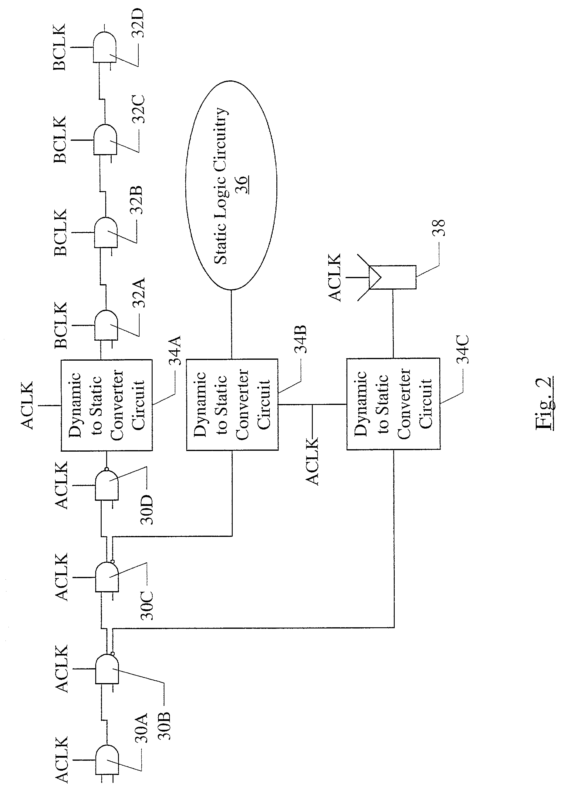
[0024] Turning now to FIG. 2, a circuit diagram illustrating one embodiment of dynamic circuitry, dynamic to static converter circuits, static logic circuitry, and a static storage device is shown. Other embodiments are possible and contemplated. More particularly, the embodiment of FIG. 2 includes a set of A-phase dynamic logic circuits 30A-30D, a set of B-phase dynamic logic circuits 32A-32D, dynamic to static converter circuits 34A-34C, static logic circuitry 36, and a static storage device 38. It is noted that, while the symbols shown on FIG. 2 for the dynamic logic circuits 30A-30D and 32A-32D resemble AND gates or NAND gates, the symbols are intended, in this context, to represent any dynamic logic circuits performing any logic function. Each dynamic logic circuit 30A-30D and 32A-32D may receive one or more inputs and generate one or more outputs in response to the inputs. Each of the dynamic logic circuits 30A-30D is coupled to receive an ACLK clock signal and has outputs cou...


PUM


Abstract

An apparatus is disclosed which includes a converter circuit and a noise suppression circuit. The converter circuit has a dynamic logic input, and is configured to generate a static logic output on an output node responsive to the dynamic logic input. The noise suppression circuit is coupled to receive a clock signal and is coupled to the output node. Responsive to a first phase of the clock signal, a precharge of a dynamic logic circuit generating the dynamic logic input occurs. The noise suppression circuit is configured to actively drive the static logic output on the output node responsive to the first phase. In some embodiments, the noise suppression circuit may reduce the noise sensitivity of the static logic output during the precharge phase, and may not impede operation of the converter circuit during the evaluate phase.

Description

[0001] 1. Field of the Invention[0002] This invention is related to the field of dynamic and static logic circuits, and more particularly to noise issues in dynamic to static conversion.[0003] 2. Description of the Related Art[0004] Dynamic logic circuits are a circuit design tool often used in integrated circuits. Generally, dynamic logic circuits are precharged to a first state and then conditionally discharged to a second state according to one or more inputs. In contrast, static logic circuits continuously respond to inputs by driving the outputs to high or low states according to the state of the inputs. Since the inputs of dynamic logic circuits are only connected to the discharge transistors (as opposed to static logic circuitry in which a given input is typically connected to at least two transistors, one which may charge the output and one which may discharge the output), the capacitive load on the inputs may be comparatively lower than equivalent static logic circuitry. Ad...

Claims


Application Information

Patent Timeline
Patent Type & Authority Applications(United States)
IPC IPC(8): H03K3/356H03K19/0185
CPCH03K19/01855H03K3/356173
Inventor CAMPBELL, BRIAN J.
Owner AVAGO TECH INT SALES PTE LTD
Why Eureka
Try Eureka