Noise and vibration suppressors

a technology of noise suppressors and suppressors, which is applied in the direction of positive displacement liquid engines, combustion air/fuel air treatment, instruments, etc., can solve the problems of noise and/or mechanical vibration, noise can lead to the vibration of a part on which noise impinges, etc., and achieve the effect of dampening vibration

Inactive Publication Date: 2006-01-10
CADILLAC RUBBER & PLASTICS
View PDF63 Cites 94 Cited by
  • Summary
  • Abstract
  • Description
  • Claims
  • Application Information

AI Technical Summary

Benefits of technology

[0017]Note that one of the chambers could have the same combination of volume and associated total aperture area as another, for example to reinforce damping at a particular noise frequency. Typically, each chamber has an optimum sound absorption frequency, preferably not less than 500 Hz, more preferably not less than 1500 Hz and preferably not higher than 8000 Hz, more preferably not higher than 5000 Hz. This is particularly suitable for suppression of turbo noise in an engine.
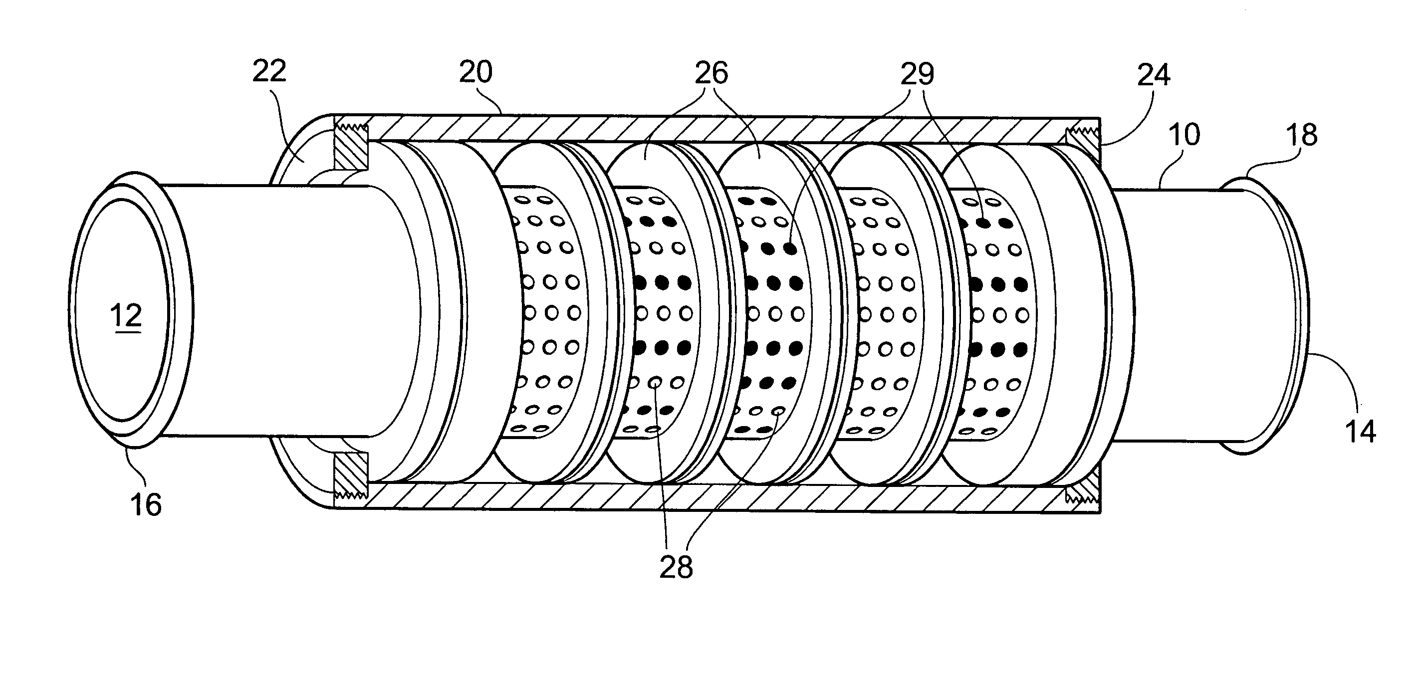
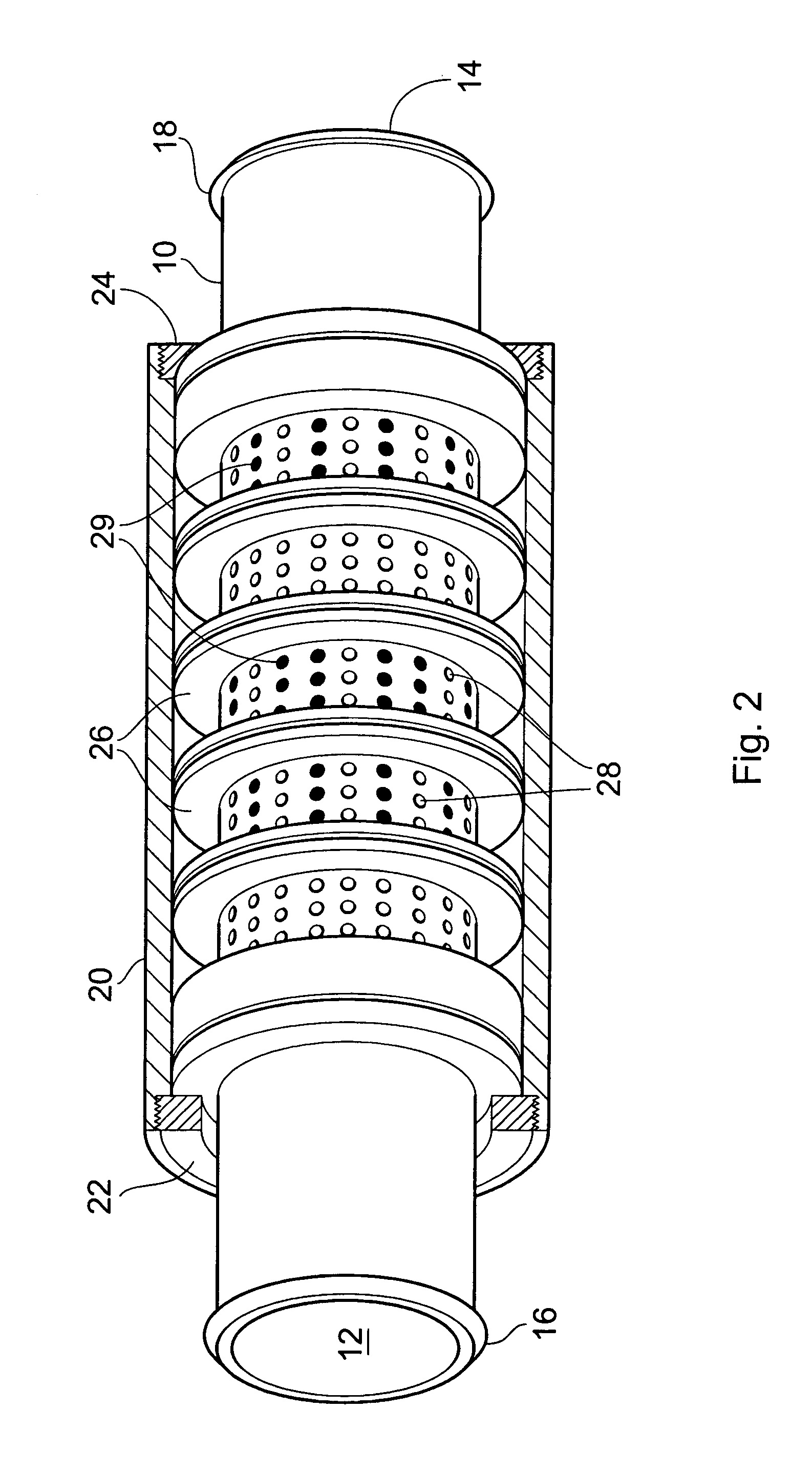
[0029]Preferably, the suppressor includes a spacer located at a gap between inner walls of adjacent modular portions. Preferably, the spacer is attachable to an end of the inner wall of one modular portion. Spacers of different axial lengths may be used. In this way, the area of the gap between inner walls of adjacent modular portions can be closed off to give a selected effective total aperture area.
[0031]The spacer may be attached to opposing faces of adjacent inner walls, for example in the case where the side walls of the modular portions are not located at either extremity of the inner walls. This has the advantage that the inner walls can be secured to each other by ensuring that both inner walls make a tight fit with the spacer. This may reduce mechanical vibration of the free ends of the inner walls, such as may be caused by air flow or other vibration-causing sources. It may reduce distortion of the free ends of the inner walls, for example due to temperature and / or long term loads, causing creep, for example. In this case, the axial projections may extend across the axial length of the spacer, so that in effect the spacer preferably forms a spacing collar between the opposing faces of adjacent inner walls, with mounting surfaces adapted to attach to the adjacent inner walls, the spacer having radial holes, slots or slits formed in it, between the axial projections. Again, the effective area of the aperture would then be controlled by the total area of apertures formed in the spacer.
[0067]A preferred feature of the first development of the invention was the location of the modular noise suppressor within a hose. The inventors have realised that the use of a modular noise suppressor within a hose is advantageous even when the chambers are wholly contained within respective modular portions. This constitutes a second, independent development of the present invention, in which it is not necessary that each suppression chamber is bounded by parts of two of said modular portions.
[0069]The disposition of a noise suppressor within a hose reduces the mechanical demands on the noise suppressor. Firstly, the noise suppressor need not be gas-tight since the hose can define a gas-tight envelope around the noise suppressor. In use, it can be a part of the hose, rather than a part of the noise suppressor, which is attached to a noise source. Typically, this noise source is part of an engine, such as an inlet or outlet of a turbo. Such connection is usually achieved using a clip or clamp, such as a jubilee-type clip. In order to maintain connection during operation, the clamping pressures used are usually high. For this reason, no noise suppressors were usually of rugged construction, typically made of metal. In this second development, the noise suppressor need not be so rugged since the clamping pressures can be withstood instead by the hose. For this reason, it is practicable to construct the noise suppressor from plastics materials which would not be able to withstand the clamping pressures as described above. The advantages of these materials include ease of forming (e.g. by injection moulding) which require little or no machining after forming to arrive at a desired shape.
[0088]Preferably, in this fifth development, the present invention provides a hose arrangement including a hose wall and an inner mass arranged in the space enclosed by the hose wall and / or the inner bore of a turbo inlet or outlet, the inner mass being separated from the interior of the hose wall or bore by resilient means so that the inner mass has a rest position towards which the resilient means urges the inner mass, the hose wall or bore and the inner mass being moveable relative to each other against the urging of the resilient means by a vibrational force, thereby to dampen the vibration. The inner mass may be wholly within the hose, partially within the hose and partially within the inner bore of the turbo inlet or outlet, or wholly within that hose.

Problems solved by technology

Motor vehicles have components which, in operation, produce noise and / or mechanical vibration.
Of course, vibration can lead to the radiation of noise from a vibrating part, and noise can lead to the vibration of a part on which the noise impinges.

Method used


Image

  • Noise and vibration suppressors
  • Noise and vibration suppressors
  • Noise and vibration suppressors

Examples


Embodiment Construction

[0107]FIG. 1 shows two vibration profiles resulting from turbo noise. The ordinate measures vibration amplitude and the abscissa indicates the frequency regime. It can be seem from FIG. 1 that, at certain frequencies, the vibration amplitudes are higher than at others. Line 2 in FIG. 1 shows the results measured from a vibration source with high vibration and high noise. Line 4 in FIG. 1 shows a measurement from a source with high vibration and low noise. It is clear from FIG. 1 that the vibration levels resulting from the high noise are higher are certain frequencies than at others. Therefore, if it is desired to reduce the levels of vibration, then it would be particularly helpful to reduce certain frequencies of vibration more than others.

[0108]FIG. 2 shows a partial sectional view of a noise suppressor according to an embodiment of the invention. Not shown in FIGS. 2 and 3 are inserts used to blank off some of apertures 28. The suppressor includes a central pipe 10 having an inl...


PUM


Abstract

In order to form a noise suppressor in a hose of e.g. a motor vehicle, modular portions are connected in series to define suppression chambers with particular noise suppression characteristics. Those characteristics are due to the volume of each chamber, to the size of the apertures from the chambers to the central duct of the suppressor, and optionally due to spacers which are inserted into at least one aperture of the chambers to alter the effective open area of that aperture. Such spacers may also be used in which the noise suppressor is not modular. Where modular portions are used, it is preferable that each chamber is bounded by parts of two modular portions. A wall of one modular portion may then close the chamber in another modular portion, making the manufacture of the modular portions easier. Also disclosed is the use of a mass acting as a damper, which may be a noise suppressor as previously discussed, within a hose. The mass is connected to the hose by resilient means, e.g. electrometric material.

Description

BACKGROUND OF THE INVENTION[0001]1. Field of the Invention[0002]The present invention relates to noise and vibration suppressors. In particular, the invention relates to such suppressors for use in motor vehicles.[0003]2. Summary of the Prior Art[0004]Motor vehicles have components which, in operation, produce noise and / or mechanical vibration. In order to prolong component life it is desirable to reduce vibration and hence reduce the vibrational stress experienced by parts of the vehicle, including parts of the engine. Furthermore, it is also desirable to reduce noise produced in the motor vehicle, usually for environmental and comfort reasons. In the context of this application, vibration or mechanical vibration is to be taken to mean unwanted oscillatory movement of a solid, for example a component of a motor vehicle. Noise is to be taken to mean unwanted sound waves in air or other fluid. Of course, vibration can lead to the radiation of noise from a vibrating part, and noise ca...

Claims


Application Information

Patent Timeline
Patent Type & Authority Patents(United States)
IPC IPC(8): F01N1/02F01N1/00F01N13/18F02M35/12F04B39/00F04D29/66F16L55/027F16L55/033G10K11/172
CPCF01N1/003F01N1/02F01N13/18F04B39/0066F04D29/665F02M35/1283F16L55/033F16L55/0335G10K11/172F02M35/1216F02M35/1266F16L55/02781F01N2470/04
Inventor BOAST, DAVIDTURNER, DONALD MILNE
Owner CADILLAC RUBBER & PLASTICS
Why Eureka
Try Eureka