
Disk subsystem

a subsystem and disk technology, applied in the direction of program control, liquid/fluent solid measurement, instruments, etc., can solve the problems of inability to continue uninterrupted operation, inability to read/write access to the hdds, and apparatus cannot meet the demands of large capacity

Inactive Publication Date: 2003-10-23
HITACHI LTD
View PDF13 Cites 6 Cited by
  • Summary
  • Abstract
  • Description
  • Claims
  • Application Information

AI Technical Summary

Problems solved by technology

However, with this structure if a failure occurs in any one of the parts, read / write access to the HDDs becomes impossible, such that the uninterrupted operation cannot be continued.
Further, due to the lack of expandability in the HDD drive section, such an apparatus cannot meet demands for large capacity.
Moreover, in order to make uninterrupted operation possible even during the process of expanding the system, all of the structures described above must be made redundant (i.e., duplicated).
This results in a complex power source boundary structure, increases the number of parts in the power source system, and makes the apparatus large.
As a result, there may be more factors that can impede uninterrupted operation, such as rising failure rate and falling reliability of the apparatus; increasingly complex power source boundary as the HDD drive section expands, making maintenance work more difficult; and greater number of errors committed in maintenance work to repair failures.
In addition, the price of the apparatus may become higher as a result of increased number of parts.
Furthermore, due to the fact that power is supplied to the HDD drive section with the power on / off operation of the HDD control logic section on a power source control by power source control basis regardless of the actual operational status of the apparatus, non-operating parts become powered even if the HDD drive section is in a non-operating state; consequently, power is wasted and the power consumption of the apparatus as a whole may not correspond to its operations.

Method used


Image

  • Disk subsystem
  • Disk subsystem
  • Disk subsystem

Examples


Embodiment Construction

[0027] An embodiment of the present invention will be described in detail below with reference to the accompanying drawings. In all of the drawings used to describe the embodiment, members having substantially the same function are assigned the same number, and descriptions of such members are not repeated.

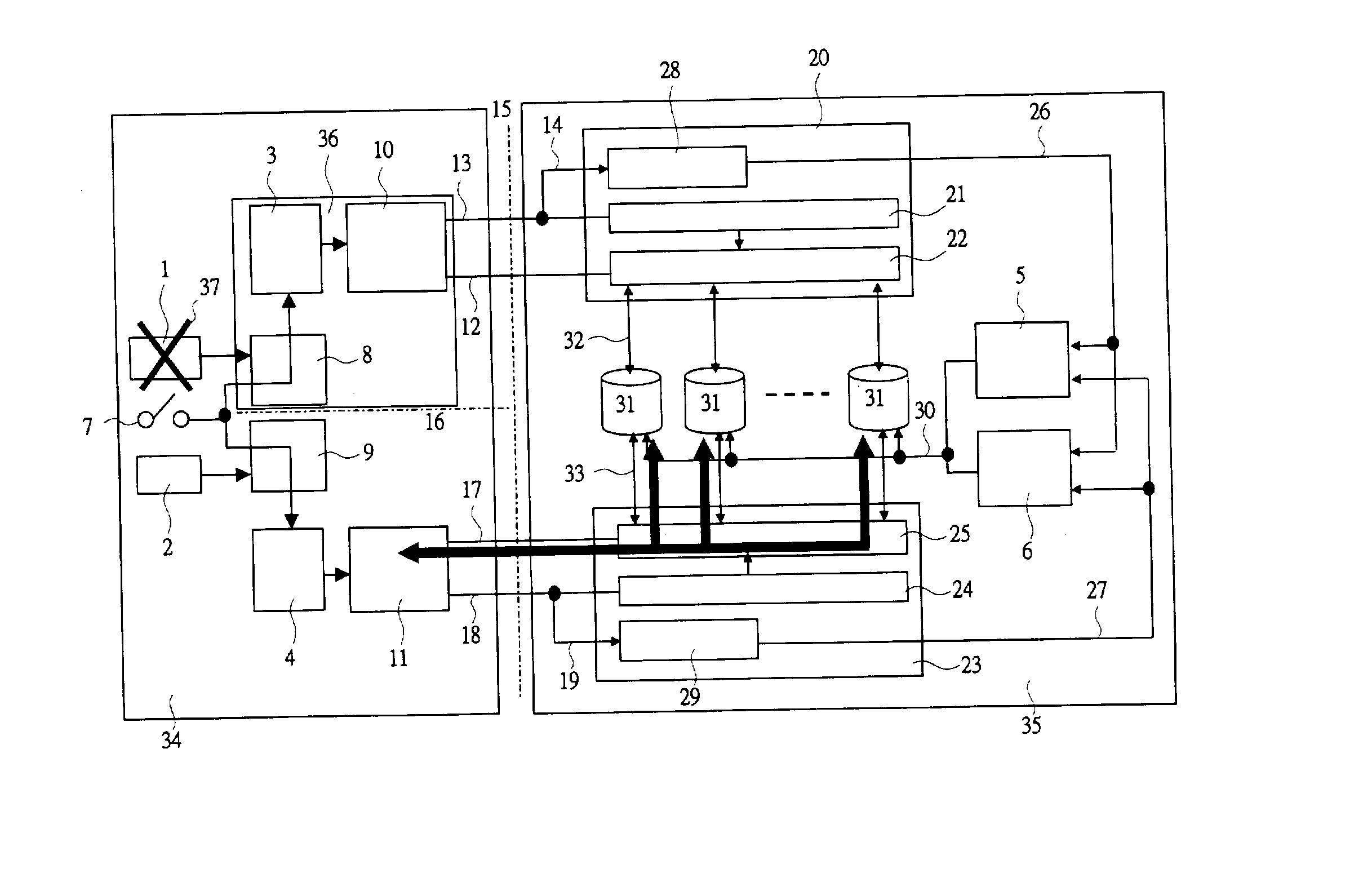
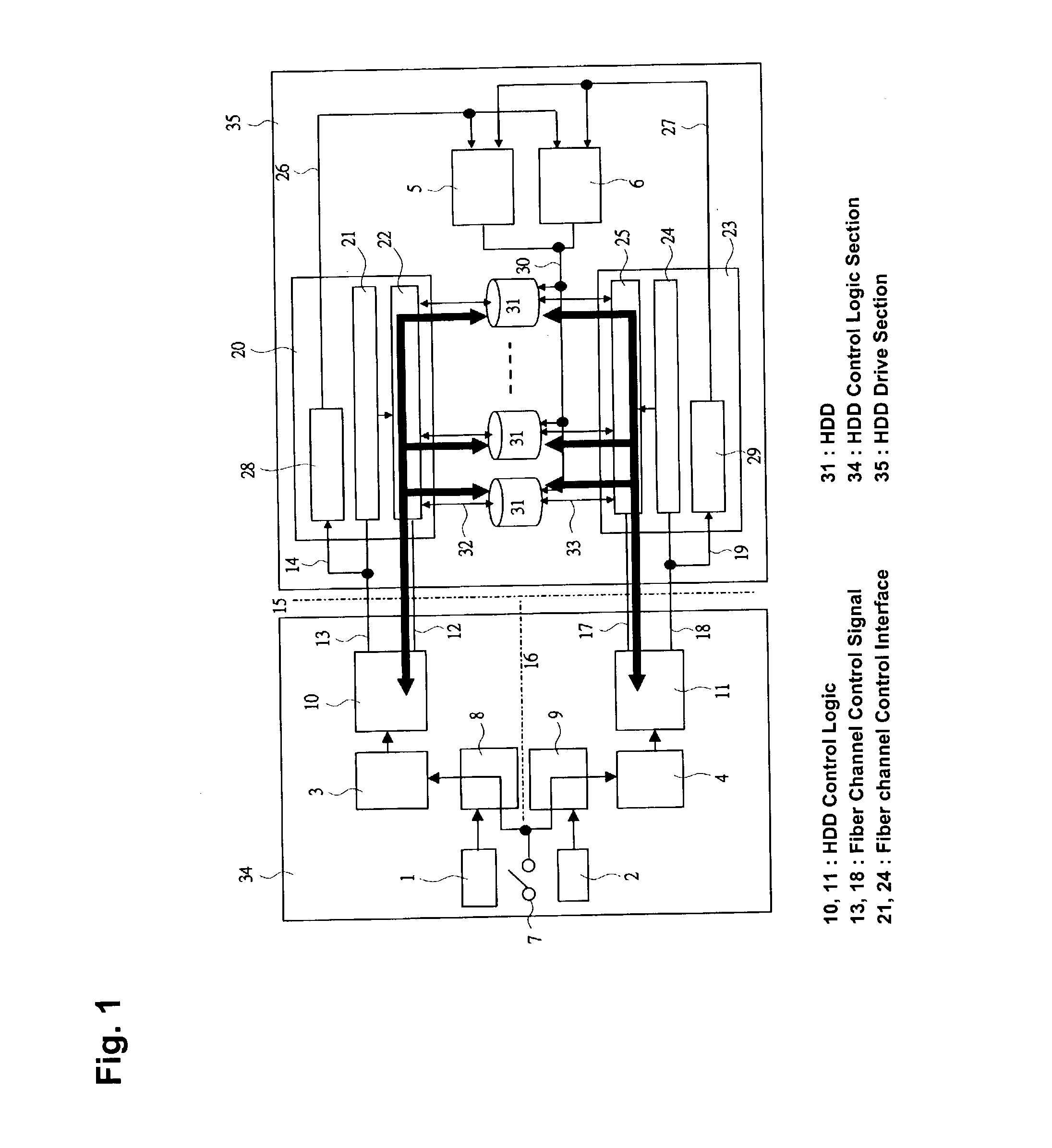
[0028] FIG. 1 is a block diagram indicating an overview of a power source control apparatus of a disk subsystem apparatus that uses fiber channel interface signals in accordance with an embodiment of the present invention.

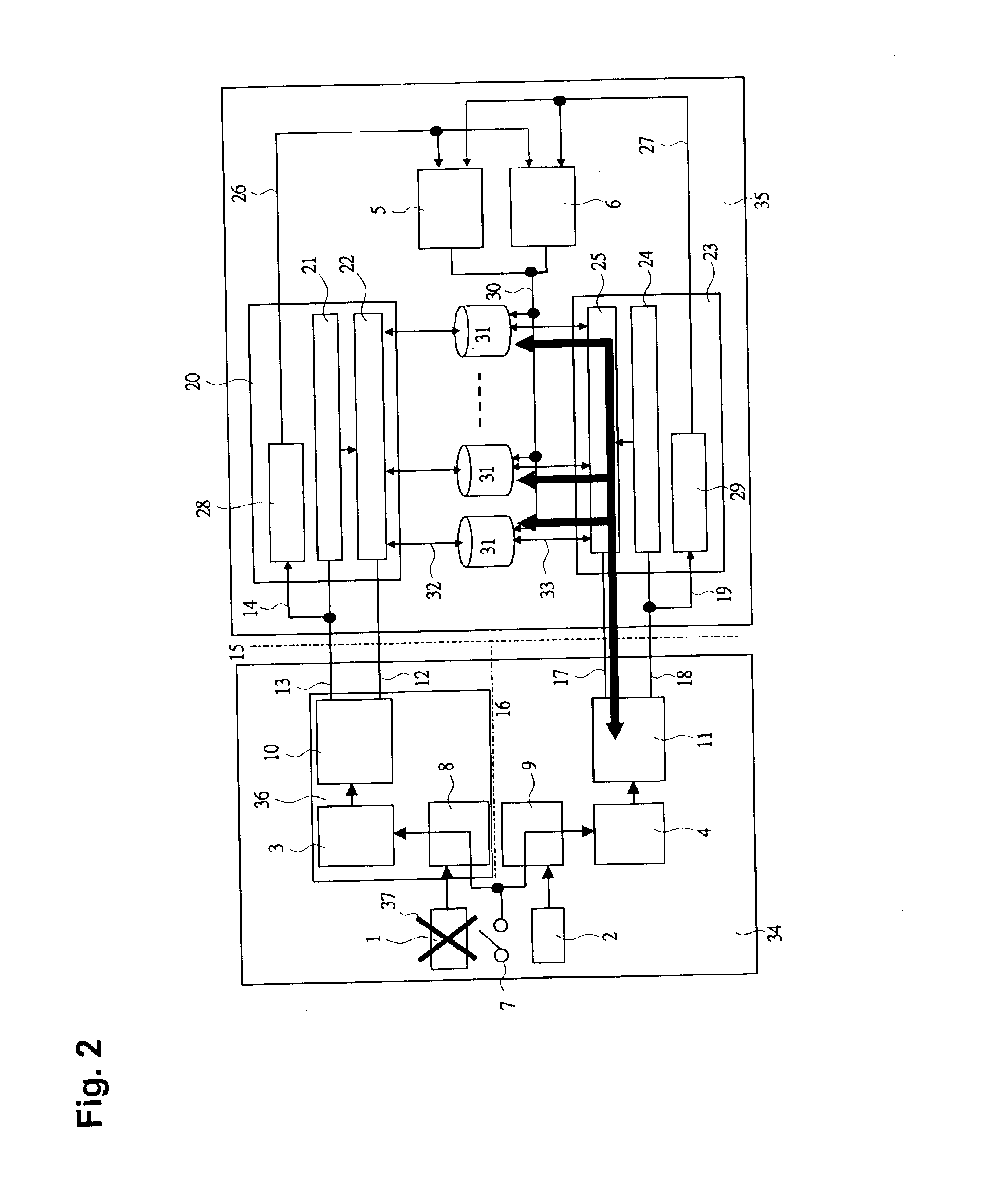
[0029] An apparatus according to the present embodiment includes an HDD control logic section 34 that controls a power source system and a data transfer system, and an HDD drive section 35 that drives HDDs each with fiber channel interface ports. The apparatus in accordance with the present embodiment is composed of a plurality of systems each having a data transfer system and a power source system (FIG. 1 indicates an example in which the apparatus consists of t...


PUM


Abstract

A power source control apparatus for a disk subsystem includes a plurality of hard disk drives (HDDs) each with two systems of fiber channel interface ports, an HDD drive section, and an HDD control logic section. The HDD drive section includes two systems of fiber channel control sections, each of which includes a fiber channel interface and a fiber channel control interface. The HDD control logic section includes two systems of HDD control logics that control read / write accesses to the HDDs. Fiber channel control signals are supplied from the HDD control logics to the fiber channel control interfaces, respectively, and the fiber channel control signals are also used to control the power source of the HDD drive section.

Description

[0001] 1. Field of the Invention[0002] The present invention relates to a disk subsystem, and a power source control apparatus for a disk subsystem and / or a disk subsystem apparatus that is operated uninterruptedly.[0003] 2. Related Background Art[0004] An existing disk subsystem apparatus is required to operate uninterrupted 24 hours a day, 365 days a year, and to have high density / large capacity through expansion of stored data. Accordingly, the following technology is conceivable for a power source control apparatus of a disk system apparatus.[0005] For example, a disk subsystem apparatus includes in its basic structure a main power source, a power source control circuit, a power source for the power source control circuit, a hard disk drive (HDD) control logic section that controls data transfer, an HDD drive section that drives HDDs with fiber channel interface ports, and a fiber channel interface.[0006] In the basic operation with this structure, when an apparatus switch is tu...

Claims


Application Information

Patent Timeline
IPC IPC(8): G06F1/30G06F3/06
CPCG06F1/30
Inventor SUZUKI, HIROSHIMATSUSHIGE, HIROMIOGAWA, MASATOYOKOYAMA, TOMOKAZU
Owner HITACHI LTD
Learn More