Method for hemming

a hemmed part and hemmer technology, applied in metal-working equipment, metal working equipment, manufacturing tools, etc., can solve the problem that the location of the inner edge will fatally affect the final geometry of the hemmed part, and achieve the effect of obtaining the overall visual appearance of a very thin hem

Inactive Publication Date: 2003-10-30
VALIANT CO LTD
View PDF2 Cites 2 Cited by
  • Summary
  • Abstract
  • Description
  • Claims
  • Application Information

AI Technical Summary

Benefits of technology

0021] The present invention, by its use not only of the initial flanging operation with a sharp bending radius between the flange and the remainder of the outer panel, but also by the use of the curvilinear prehemming tool, ensures that the outer bend line for the outer panel remains fixed during the entire hemming operation. By so fixing the position of the outer bend line, cracking of the outer panel along the bend line is avoided and panels of predictable and consistent sizes are obtained. As a further advantage, the present invention eliminates essentially all creeping of the outer panel during the prehemming operation as well as any recoil resulting of this initial creeping when performing the final hem. By eliminating such creeping, the overall visual appearance of a very thin hem is obtained.

Problems solved by technology

Consequently, any variation in the location of the inner edge will fatally impact on the final geometry of the hemmed part.

Method used


Image

  • Method for hemming
  • Method for hemming
  • Method for hemming

Examples


Embodiment Construction

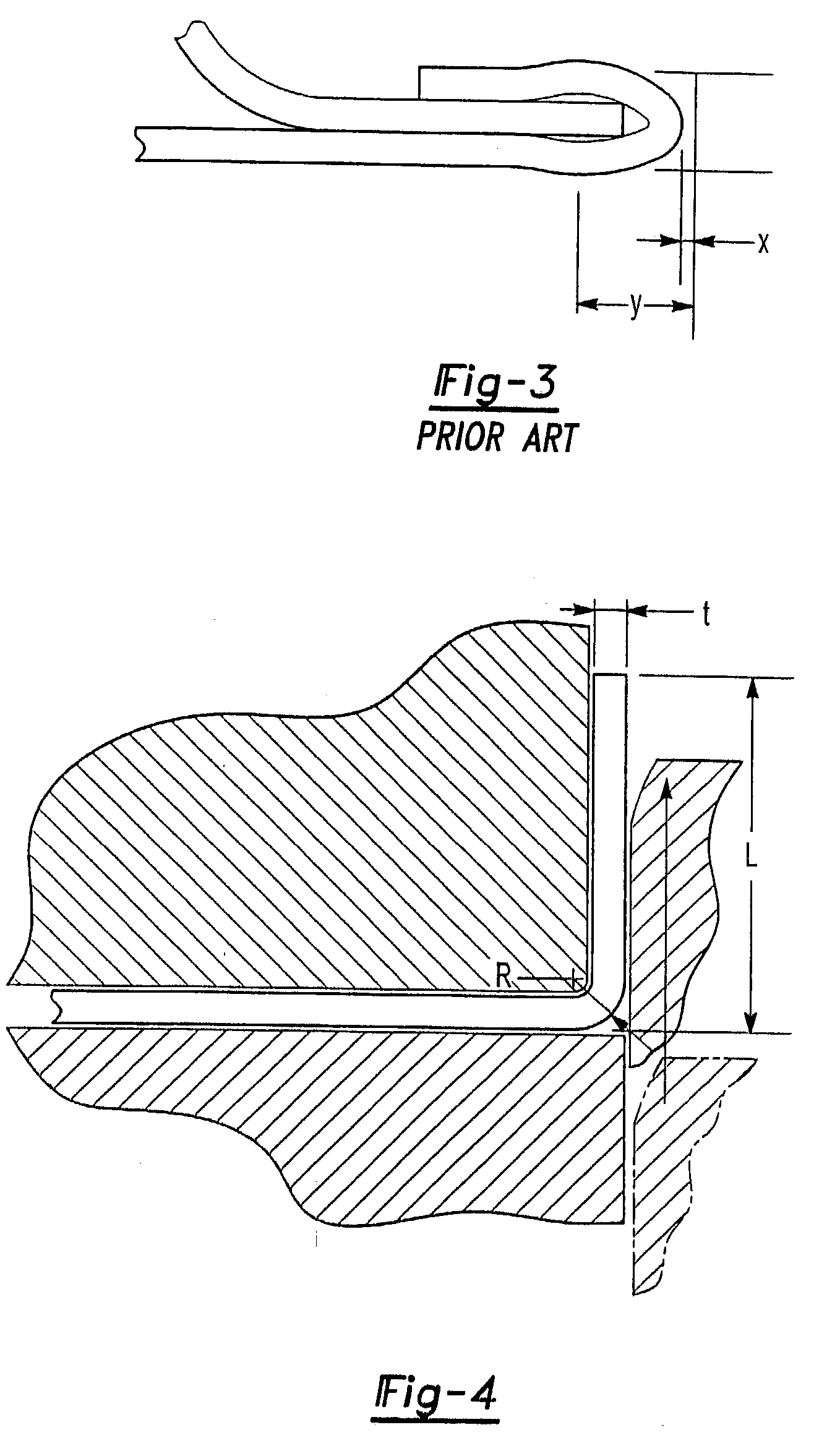
[0030] With reference first to FIG. 4, during the hemming method of the present invention, a flange 10 is first formed around an outer peripheral portion of an outer panel 12. Consequently, the flange 10 extends from a bend line 14 formed in the outer panel 12 such that the flange 10 lies in a plane generally perpendicular to the plane of the remainder 16 of the outer panel 12. The flange 10, furthermore, has an overall width of L.

[0031] Unlike the previously known hemming methods, the bend line 14 has an outer radius R in the range of (1.0 mm+t)>R>(0.2 mm+t) where t=the thickness of the outer body panel 12. Since aluminum panels 12 are generally from 0.8 mm to 1.2 mm in thickness, the radius R between the flange 10 and remainder 16 of the outer panel 12 along the bend line 14 will be typically in the range of 1.4 mm to 2.2 mm for a 1.2 mm thick panel.

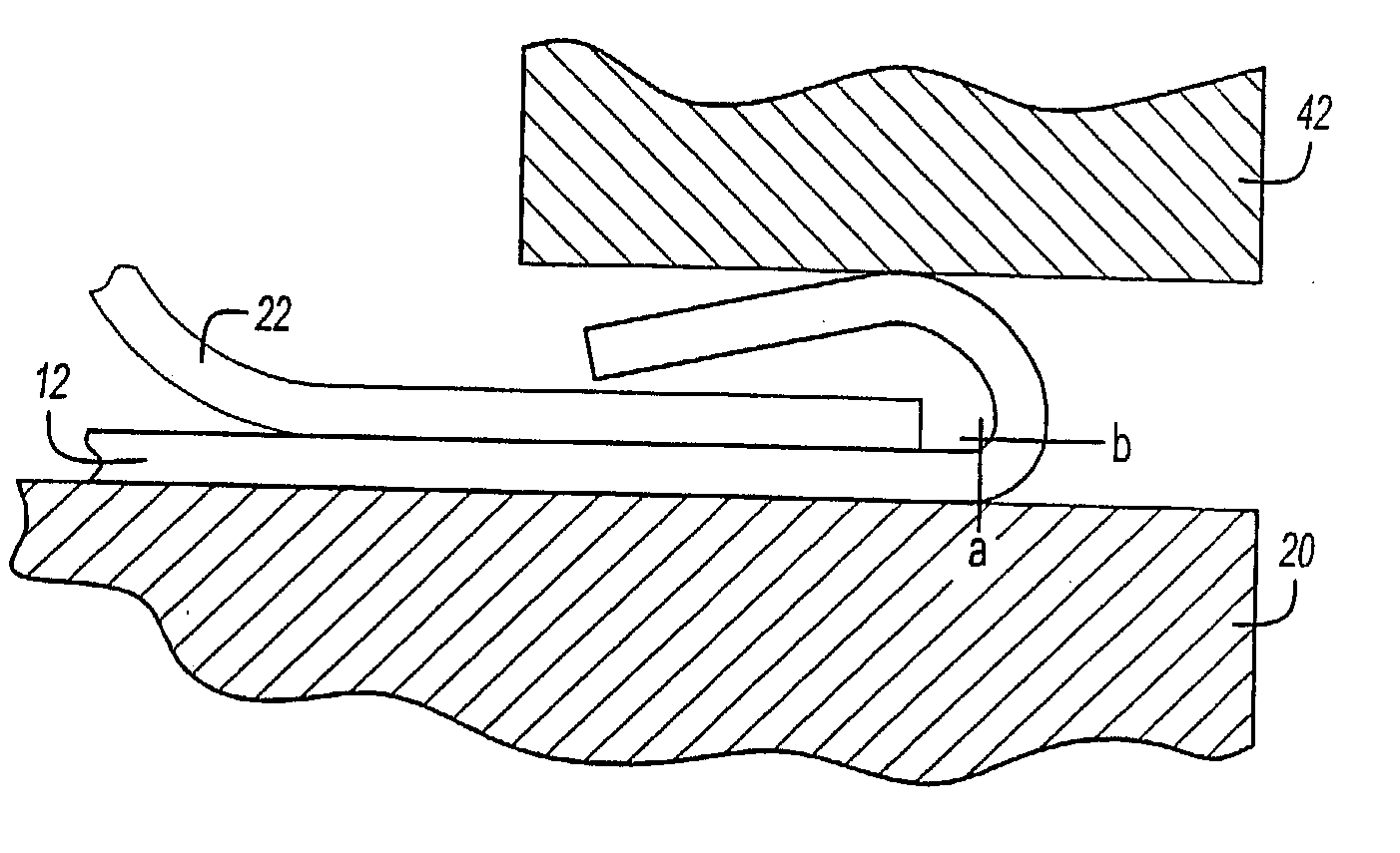
[0032] With reference now to FIGS. 5A and 5B, following the flanging operation, the outer panel 12 is positioned on a nest 20 (illust...


PUM

PropertyMeasurementUnit
angleaaaaaaaaaa
angleaaaaaaaaaa
widthaaaaaaaaaa

Abstract

A method for sharp, crisp hemming inner and outer aluminum sheet metal panels in which a flange is formed along an outer edge so that the flange extends from a bend line and lies in a plane generally perpendicular to the plane of the outer panel. This bend line, furthermore, has an outer radius in the range of (1.0 mm+t)>R>(0.2 mm+t) where t=the thickness of the outer panel. The inner panel is then positioned on the outer panel so that an outer edge of the inner panel is adjacent the bend line. The flange is then bent so that the flange overlies the outer edge of the inner panel while simultaneously compressing the flange in the direction towards the bend line. Thereafter, the flange is compressed against the outer peripheral portion of the inner panel thus completing the hem. The present invention thus achieves a sharp radius bend on the outer edge of the panel with a layer radius bend on the inner panel as well as a class "A" surface on the outer panel adjacent the hem which is free of recoil or other distortion.

Description

[0001] I. Field of the Invention[0002] The present invention relates generally to a method for producing a flat hem with a very sharp radius bend between two sheet metal panels for use primarily as automotive closure.[0003] II. Description of Related Art[0004] There are many previously known hemming machines and hemming methods. Many industries, such as the automotive industry, utilize sheet metal hemming machines to secure two metal panels together. For example, in constructing a door for an automotive vehicle, the door typically comprises both an outer panel and an inner panel. In order to secure these panels together, a hem is formed between the inner and outer panel around the outer peripheral edge of the panels such that an outer edge portion of the inner panel is sandwiched in between a flange on the outer panel and the outer panel itself.[0005] In order to perform the hemming operation, there are many previously known hemming machines. These hemming machines typically compris...

Claims


Application Information

Patent Timeline
Patent Type & Authority Applications(United States)
IPC IPC(8): B21D39/02
CPCY10T29/53791B21D39/021B21D39/02
Inventor BAULIER, DOMINIQUE
Owner VALIANT CO LTD
Why Eureka
Try Eureka