
Packing case and packing method for packing image forming apparatus, and image forming apparatus

a technology of image forming apparatus and packing case, which is applied in the directions of packaging foodstuffs, packaging goods type, transportation and packaging, etc., can solve the problems of high cost, increase in shipment cost, and unavoidable excess packing

Active Publication Date: 2003-11-13
SHARP KK
View PDF5 Cites 35 Cited by
  • Summary
  • Abstract
  • Description
  • Claims
  • Application Information

AI Technical Summary

Benefits of technology

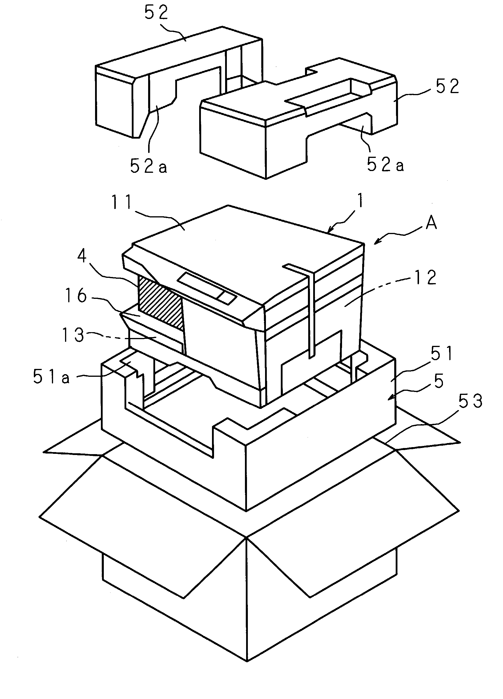
[0067] According to the fourth aspect of the packing method of the present invention for an image forming apparatus, since the packed drum unit is inserted and fixed in the sheet storage space, it is possible to effectively use the sheet storage space where no sheet is stored at the time of packing, thereby achieving a decrease in the size of the packing case for the image forming apparatus and a reduction in the cost of the packing case. In addition, the reading section of the image forming apparatus can be supported by the drum unit inserted and fixed in the sheet storage space, and a shock absorbing material for use exclusively in the sheet storage space is unnecessary, thereby improving the packing performance.
[0069] According to the fifth aspect of the packing method of the present invention for an image forming apparatus, since the packed photosensitive drum and toner cartridge are inserted and fixed in the sheet storage space, it is possible to effectively use the sheet storage space where no sheet is stored at the time of packing, thereby achieving a decrease in the size of the packing case for the image forming apparatus and a reduction in the cost of the packing case. In addition, the reading section of the image forming apparatus can be supported by the photosensitive drum and toner cartridge inserted and fixed in the sheet storage space, and a shock absorbing material for use exclusively in the sheet storage space is unnecessary, thereby improving the packing performance.
[0071] According to the first aspect of the image forming apparatus, since the image forming apparatus main body is packed by a first packing member and the toner cartridge packed by the second packing member formed to be inserted and fixed in the sheet storage space of the image forming apparatus main body packed by the first packing member, it is possible to decrease the overall size of the packing case and reduce the cost of the packing case.
[0079] According to the fifth aspect of the image forming apparatus of the present invention, since the second packing member for packing the drum unit is inserted and fixed in the sheet storage space, it is possible to decrease the overall size of the packing case and reduce the cost of the packing case. Moreover, since the second packing member is inserted and fixed in the sheet storage space, this second packing member can support the reading section and a shock absorbing member for use exclusively in the sheet storage space is unnecessary, thereby improving the packing performance.

Problems solved by technology

However, since the number of packages for a single image forming apparatus increases, there is the problem of an increase in the shipment cost.
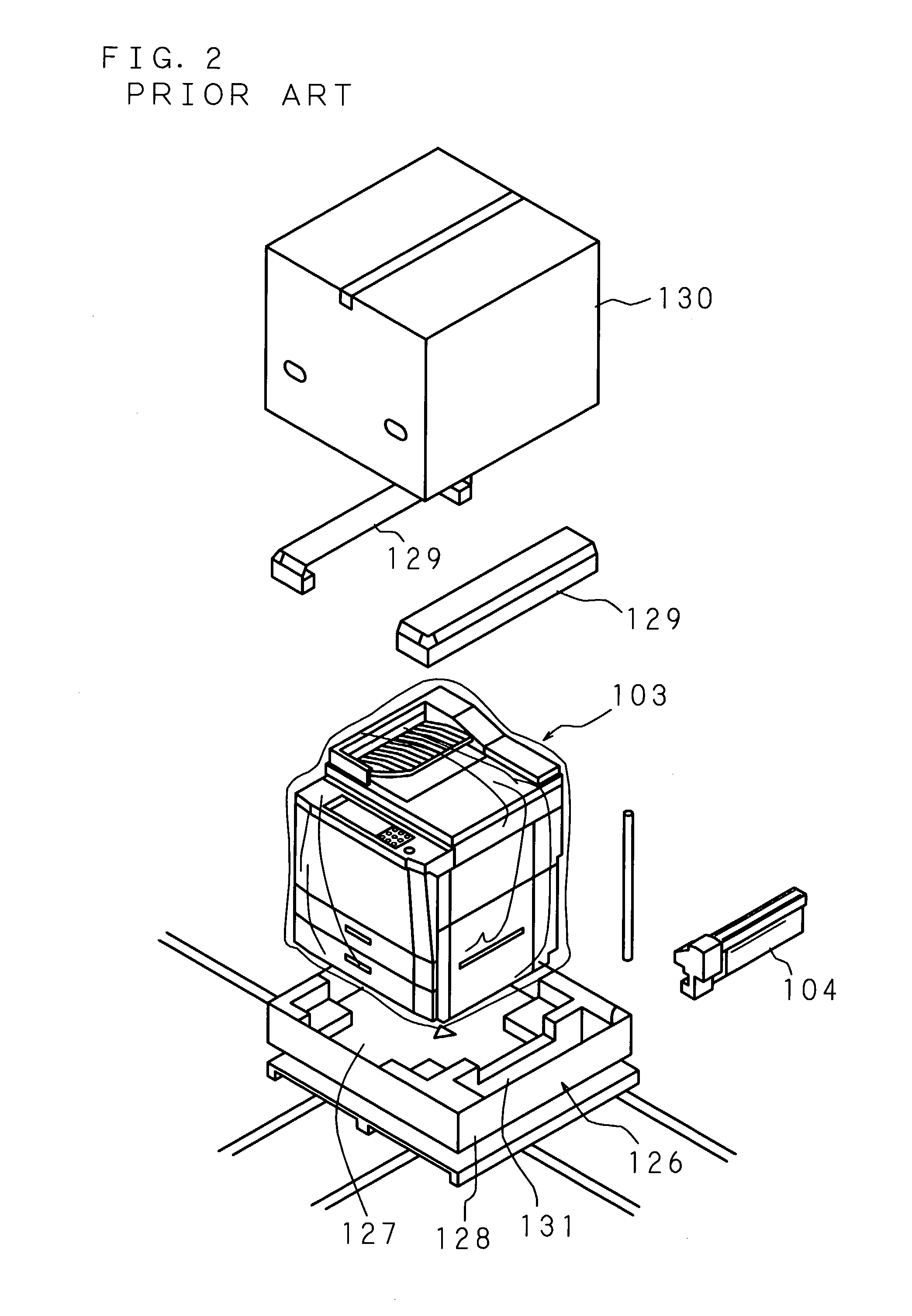
Further, as shown in FIG. 2 and FIG. 4, in the conventional packing methods in which the recessed portions 131, 144 for packing the toner cartridges 104, 138 are formed outside the packing area for the image forming apparatus main bodies 103, 137, although sufficient shock resistance is provided, excessive packing is unavoidable as a large quantity of packing material is necessary, and thus there is the problem of high cost.
In addition, since the overall volume of the packing case increases, there is also the problem of high shipment cost.

Method used


Image

  • Packing case and packing method for packing image forming apparatus, and image forming apparatus
  • Packing case and packing method for packing image forming apparatus, and image forming apparatus
  • Packing case and packing method for packing image forming apparatus, and image forming apparatus

Examples


Embodiment Construction

[0094] The following description will explain the present invention in detail, based on the drawings illustrating some embodiments thereof.

[0095] FIG. 5 is a schematic view showing the structure of an image forming apparatus of the present invention to be packed by a packing case of the present invention.

[0096] As shown in FIG. 5, this image forming apparatus A comprises a reading section 11 having a scanner unit 11a for reading a document image; an image forming unit 12 for forming an image according to image data read by the reading section 11; and a sheet feed unit 13 for feeding a sheet to the image forming unit 12. The reading section 11 and the sheet feed unit 13 are disposed to face each other with a space therebetween in upward and downward, and the image forming unit 12 is disposed on one end portion side of the space between the facing reading section 11 and sheet feed unit 13. The image forming unit 12 and sheet feed unit 13 constitute an image forming section 14. Besides...


PUM

PropertyMeasurementUnit
Sizeaaaaaaaaaa

Abstract

A packing case for an image forming apparatus, comprising: a first packing member 5 for packing an image forming apparatus main body 1 including a reading section 11 having a scanner unit for reading a document image, an image forming section 14 having an image forming unit 12 for forming an image according to image data and a sheet feed unit 13 for feeding a sheet to the image forming unit 12, and a sheet storage space 16, formed to be open to outside between the reading section 11 and the image forming section 14, for storing a sheet transported from the image forming unit 12; and a second packing member 4 for packing a toner cartridge 2 containing toner to be supplied to the image forming unit 12 and capable of being inserted into and removed from the image forming apparatus main body 1, in which the second packing member 4 is inserted and fixed in the sheet storage space 16. This packing case enables a decrease in the overall size of the packing case and a reduction in the cost of the packing case.

Description

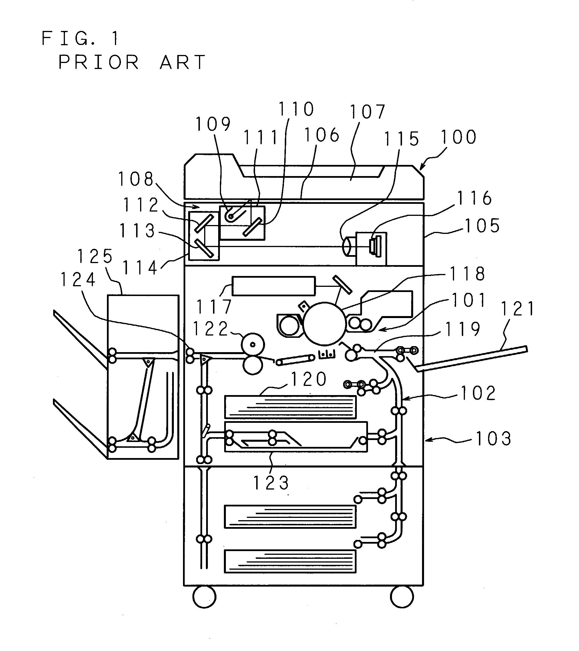
[0001] 1. Field of the Invention[0002] The present invention relates to a packing case and a packing method, for packing an image forming apparatus which forms an image according to image data read by a reading section having a scanner unit, and to an image forming apparatus packed by such packing case.[0003] 2. Description of Related Art[0004] As conventional image forming apparatuses, there are mainly two types of known image forming apparatuses. One type is a large image forming apparatus which is relatively high in height and installed mainly on a floor, and the other type is a small image forming apparatus which is relatively short in height and placed on a stand such as a cabinet.[0005] FIG. 1 is a schematic view showing an example of the structure of a conventional large image forming apparatus. A main component of a conventional image forming apparatus of this type is an image forming apparatus main body 103 including a reading section 100 having a scanner portion for readin...

Claims


Application Information

Patent Timeline
IPC IPC(8): B65D77/26B65D85/68B65D81/113
CPCB65D2585/6892B65D81/113
Inventor OTSUKA, YOSHINORISANADA, YOSHIAKIMIHARA, KOUICHIYONEDA, HARUKO
Owner SHARP KK
Learn More