Wearable computing system, method and device

a computing system and wrist-wearable technology, applied in the field of wearable electronic systems and devices, physical therapy devices, solar energy collectors, automobile dashboards, etc., can solve the problems of not providing a convenient hand-held interface, no wrist-wearable docking mechanism, and unsatisfactory results

Inactive Publication Date: 2003-11-13
SEARCH & SOCIAL MEDIA PARTNERS
View PDF99 Cites 86 Cited by
  • Summary
  • Abstract
  • Description
  • Claims
  • Application Information

AI Technical Summary

Problems solved by technology

But these devices are not ideal in that they do not provide a convenient manual interface for the hand of the arm upon which the device is worn.
Moreover, no wrist-wearable docking mechanism, whereby numerous attachments can be interchanged for wrist-wearable use using the same arm attachment mechanism, is provided, nor is a system of movable couplings that is sufficient to allow swiveling, tilting, revolving, and / or linear movement of entire electronic devices, such as telephones or credit card readers, while being worn on the arm.
However, Moore provides no means for retracting this keypad under the user's sleeve when not in use nor any means for using these keys to control or interact with swiveling, tilting, or otherwise movable, wrist-wearable electronic components.
Existing devices used to protect or treat the human hand, wrist or forearm often do as much damage as they do good.
However, Working introduces other problems.
Moreover, braces that resist the motion of the wrist and fingers have a second unintended, potentially harmful result: in resisting flexing of the wrist and fingers, a brace can serve as a "Iresistance training" device against which the spasming hand and forearm muscles of a CTS sufferer can push, thereby further aggravating the overdevelopment of these muscles.
Existing solutions also include highly invasive surgeries that cost CTS sufferers a great deal of time, money and pain and which are associated with a high degree of risk of further damage to the patient's hand or wrist.
What is also needed is a device that deters but does not prevent motion and does not provide resistance to the flexor muscles of the hand and fingers sufficient to allow a user to continue to build up the hand and forearm muscles unintentionally.
Solar panels for use on rooftops are commonly known, but inhabitants of multistory apartments and condominium buildings typically do not have access to or control of the roofs of buildings.
Many automobile owners do not work on their own cars and forget to have the filter changed by someone else.
Meanwhile, the aftermarket solution is clearly not as aesthetically pleasing as an OEM solution would be; sticking filters to the dashboard of a car diminishes the intended appearance of that dashboard.
Conventional automobile odometers and license plates are not ideal in that they require the reading of actual numerical digits by an observer or an instrument, such as a camera or scanner.
This device is nonetheless less than ideal in that it is still too complicated to be read at large distances.

Method used


Image

  • Wearable computing system, method and device
  • Wearable computing system, method and device
  • Wearable computing system, method and device

Examples


Embodiment Construction

, taken together with the drawings, in which:

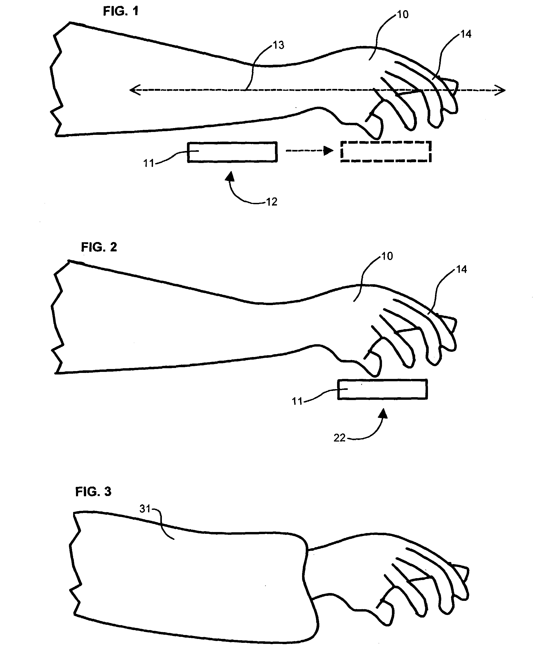
[0027] FIG. 1 depicts a side view of a user interface device in wrist-adjacent position, from which position the device can move in a line which is substantially parallel to a depicted line described by the user's forearm to the position depicted in FIG. 2.

[0028] FIG. 2 depicts a side view of a user interface device in palm-adjacent position.

[0029] FIG. 3 depicts a side view of a user's shirt sleeve covering a user interface device in wrist-adjacent position.

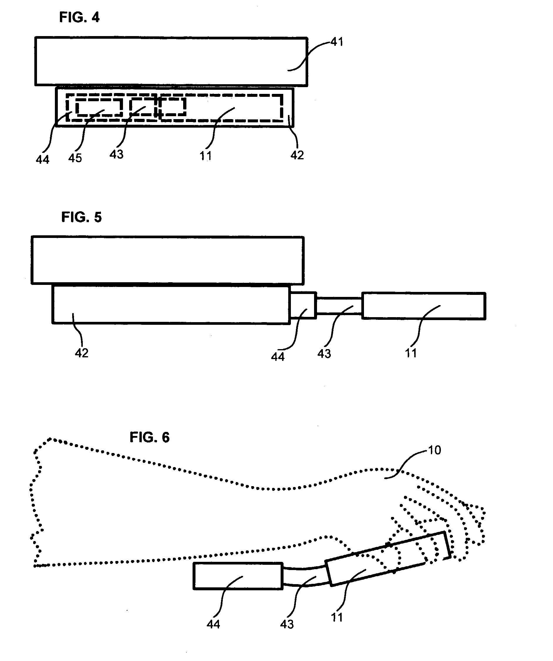
[0030] FIGS. 4 and 5 depict a side view of the basic parts of a wrist-wearable apparatus that supports a user interface device in such a way as to allow it to move from wrist-adjacent to palm-adjacent position.

[0031] FIG. 6 depicts a side view of the movable components of a wrist-wearable device being worn and manipulated by a user.

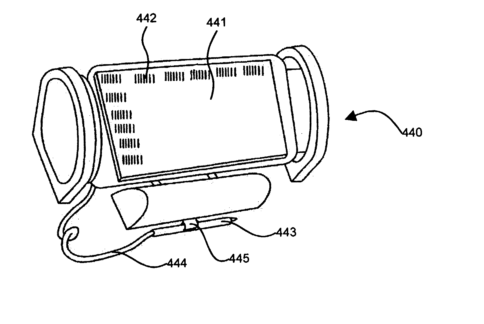
[0032] FIGS. 7 and 8 depict a perspective view of a wrist-wearable audio recorder in use, wherein a keypad for manual input of electronic data is provided ...


PUM


Abstract

Disclosed is a wrist-wearable electronic interface movably mounted on an arm-attachment mechanism. Interface moves from under-sleeve wrist-adjacent position to palm-adjacent position where it can be manipulated by the hand of the arm wearing the device. Alternately adaptable to telephones, audio recorders, remote controls, auto ID equipment, telephone call-blocking, and more. Alternative embodiment provides a wrist-mounted docking station. Another alternative embodiment includes a superior carpal tunnel syndrome therapy device. The system also includes novel battery chargers: (1) window-mounted, solar-powered; (2) mounted in an automobile that also includes an improved odometer, license plate, and cabin air filtration system.

Description

[0001] This application is a continuation-in-part of U.S. patent application Ser. No. 09 / 724,701, filing date Nov. 28, 2000, which was a continuation of U.S. patent application Ser. No. 09 / 117,150, which has now matured into U.S. Pat. No. 6,184,804. The latter application was the United States national case filing of PCT filing PCT / US97 / 01356, filing date Jan. 22, 1997, which claimed the priority filing date of provisional patent application No. 60 / 010,648, filed on Jan. 26, 1996. This application also claims the priority filing date of provisional patent application No. 60 / 381,624, filed May 17, 2002; provisional patent application No. 60 / 383,526, filed May 28, 2002; and provisional patent application No. 60 / 395,367, filed Jul. 12, 2002. All of these related applications are hereby incorporated by reference in their entirety into the present disclosure.STATEMENT REGARDING FEDERALLY SPONSORED RESEARCH AND DEVELOPMENT[0002] None.REFERENCE TO SEQUENCE LISTING, A TABLE, OR A COMPUTER P...

Claims


Application Information

Patent Timeline
Patent Type & Authority Applications(United States)
IPC IPC(8): G04B25/00G04C17/00G04G9/02G04G9/06G06F1/16G06F3/02G06F3/023G06K7/10G06K17/00
CPCG04B25/00G04C17/00G04G9/02G04G9/06G07F17/3209G06F3/0213G06F3/0219G06K7/10891G06K17/00G06F1/163
Inventor HARRISON, SHELTON E. JR.
Owner SEARCH & SOCIAL MEDIA PARTNERS
Why Eureka
Try Eureka