Cup assembly

a technology for cups and cups, applied in the field of cups, can solve the problems of limited assistance for infants or children, leakage of liquid stored in cups, and leakage of drinking orifices and air vents

Inactive Publication Date: 2003-11-27
ANGELCARE FEEDING USA LLC
View PDF42 Cites 49 Cited by
  • Summary
  • Abstract
  • Description
  • Claims
  • Application Information

AI Technical Summary

Problems solved by technology

The bottles provide limited assistance to infants or children because they do not allow for a complete or nearly complete closure of the infants hand

Method used


Image

  • Cup assembly
  • Cup assembly
  • Cup assembly

Examples


Embodiment Construction

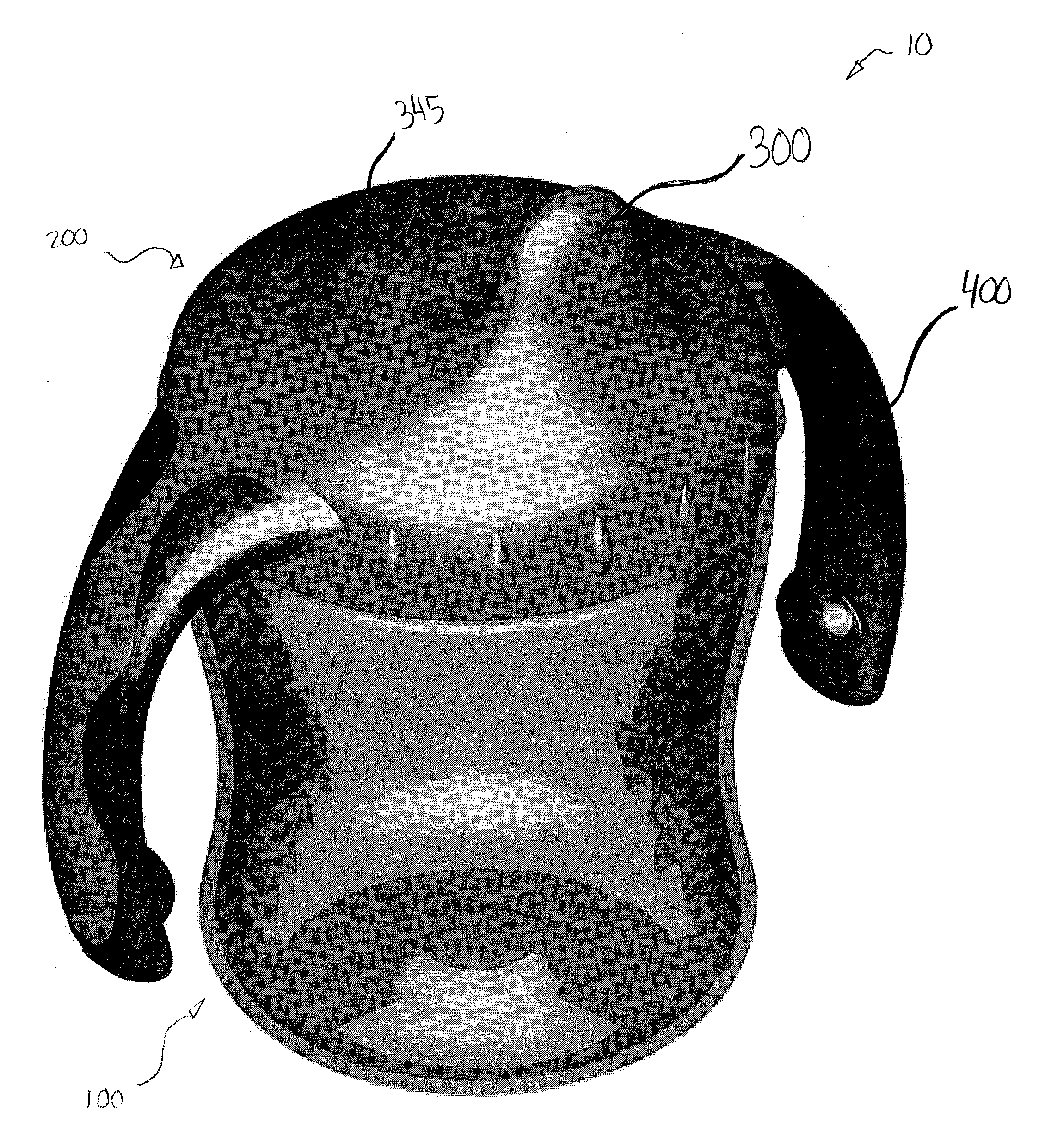
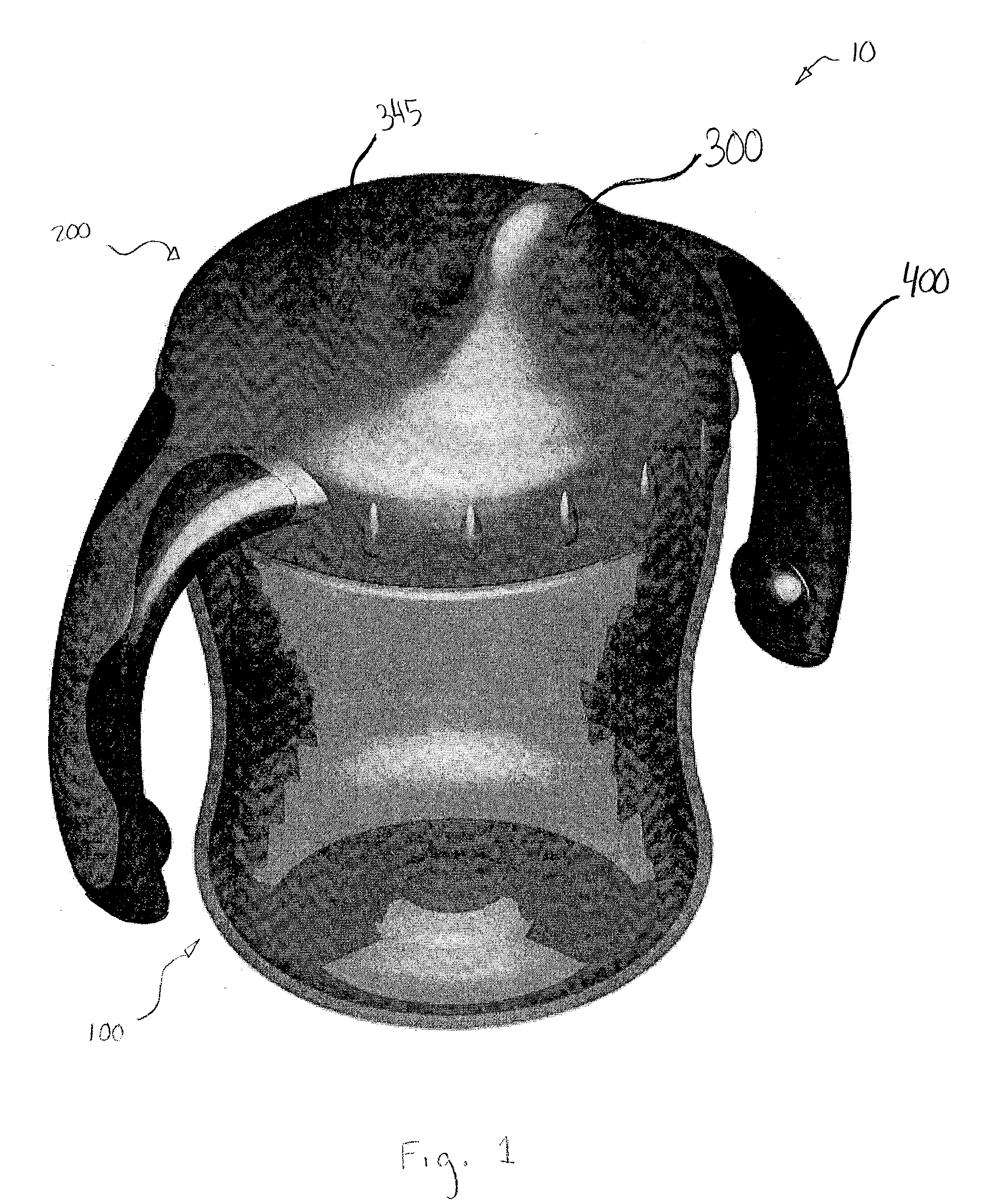
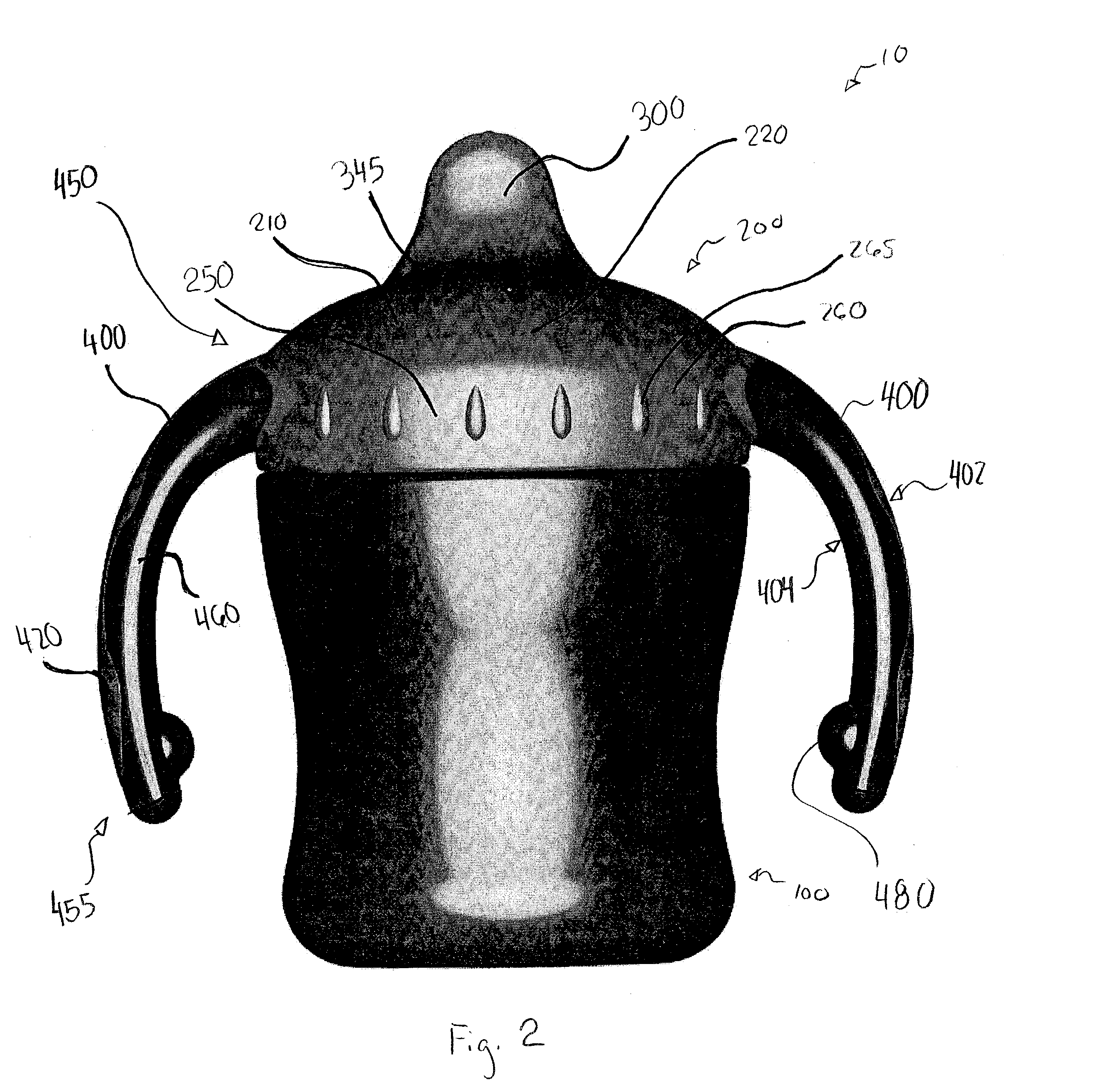
[0049] Referring to the drawings and, in particular, FIGS. 1 through 4, there is shown a preferred embodiment of a cup assembly of the present invention, generally represented by reference numeral 10. Cup assembly 10 has a cup or container 100, a cap or lid 200, a spout 300 extending from the lid, and a valve or flow control element 700 (FIG. 4).

[0050] Referring to FIG. 5, cup 100 has a substantially cylindrical shape defining an inner volume 105. Cup 100 has a top portion 110 having an open end 115, a middle portion 140 and a bottom portion 160. Middle portion 140 can have a diameter that is smaller than the diameter of top portion 110 or bottom portion 160 to provide an hour-glass like shape. Alternative shapes can also be used for cup 100, such as, for example, tapered.

[0051] Top portion 110 has an outer surface 120 with threads 125 formed thereon. The preferred embodiment has threads 125 for removably engaging lid 200 with cup 100. However, alternative engagement structures or m...


PUM

PropertyMeasurementUnit
Flow rateaaaaaaaaaa
Volumeaaaaaaaaaa
Shapeaaaaaaaaaa

Abstract

A cup is provided having a lid with a spout defined by walls tapered towards a distal end of the spout. The lid has handles extending therefrom that are preferably formed of a first and second material having different Shore A hardnesses to define a rigid portion and a gripping portion.

Description

[0001] This application is a continuation-in-part of, and claims priority in, co-pending U.S. Design Application Ser. No. 29 / 168,356, filed Oct. 1, 2002, the disclosure of which is incorporated in its entirety herein by reference. This application is also a continuation-in-part of, and claims priority in, co-pending U.S. application Ser. No. 09 / 908,099, filed Jul. 18, 2001, which is a continuation-in-part of prior U.S. patent application Ser. No. 09 / 645,975 filed on Feb. 4, 2000 and issued as U.S. Pat. No. 6,422,415, which was a continuation of prior U.S. patent application Ser. No. 09 / 019,765 filed on Feb. 6, 1998 and issued as U.S. Pat. No. 6,050,445, the disclosures of which are incorporated in their entirety herein by reference.[0002] 1. Field of the Invention[0003] The present invention relates to cups. More particularly, the present invention relates to infant cup assemblies.[0004] 2. Description of the Prior Art[0005] Cups designed especially for use by infants or children ar...

Claims


Application Information

Patent Timeline
IPC IPC(8): A47GA47G19/22B29C45/16B65D23/10B65D47/20B65D51/16
CPCA47G19/2272B29C45/1676B29L2031/463B65D51/165B29L2031/7158B65D23/10B65D47/2031B29L2031/56B65D25/28B65D47/06B65D47/32B65D51/1644B65D51/242B65D2525/283
Inventor RANDOLPH, ROSS STEVENSEJNOWSKI, JOSEPH PAUL
Owner ANGELCARE FEEDING USA LLC
Why Eureka
Try Eureka