
Electronic source inspection process

a technology of electronic source and inspection process, which is applied in the direction of instruments, data processing applications, computing, etc., can solve the problems of increasing the cost of the contractor in several respects, affecting the quality of the components, and requiring additional indirect costs

Inactive Publication Date: 2003-12-04
NORTHROP GRUMAN CORP
View PDF9 Cites 15 Cited by
  • Summary
  • Abstract
  • Description
  • Claims
  • Application Information

AI Technical Summary

Problems solved by technology

Travel by inspectors to each manufacturer's site increases the contractor's costs in several respects.
First, travel expenditures of each inspector are a significant part of the component manufacturing costs.
An indirect cost is additionally incurred whenever an inspector is absent from the contractor's site and is, therefore, unavailable for inspection of components upon receipt or during the integration process.
However, this is often difficult or impossible to achieve if the examiner must make source inspections at one or more widely separated manufacturing sites.
This not only results in a saving in travel costs, but also frees the inspector's time for related tasks, such as physical inspection and testing of components received from the manufacturing site.

Method used


Image

  • Electronic source inspection process
  • Electronic source inspection process
  • Electronic source inspection process

Examples


Embodiment Construction

, taken in conjunction with the accompanying drawings.

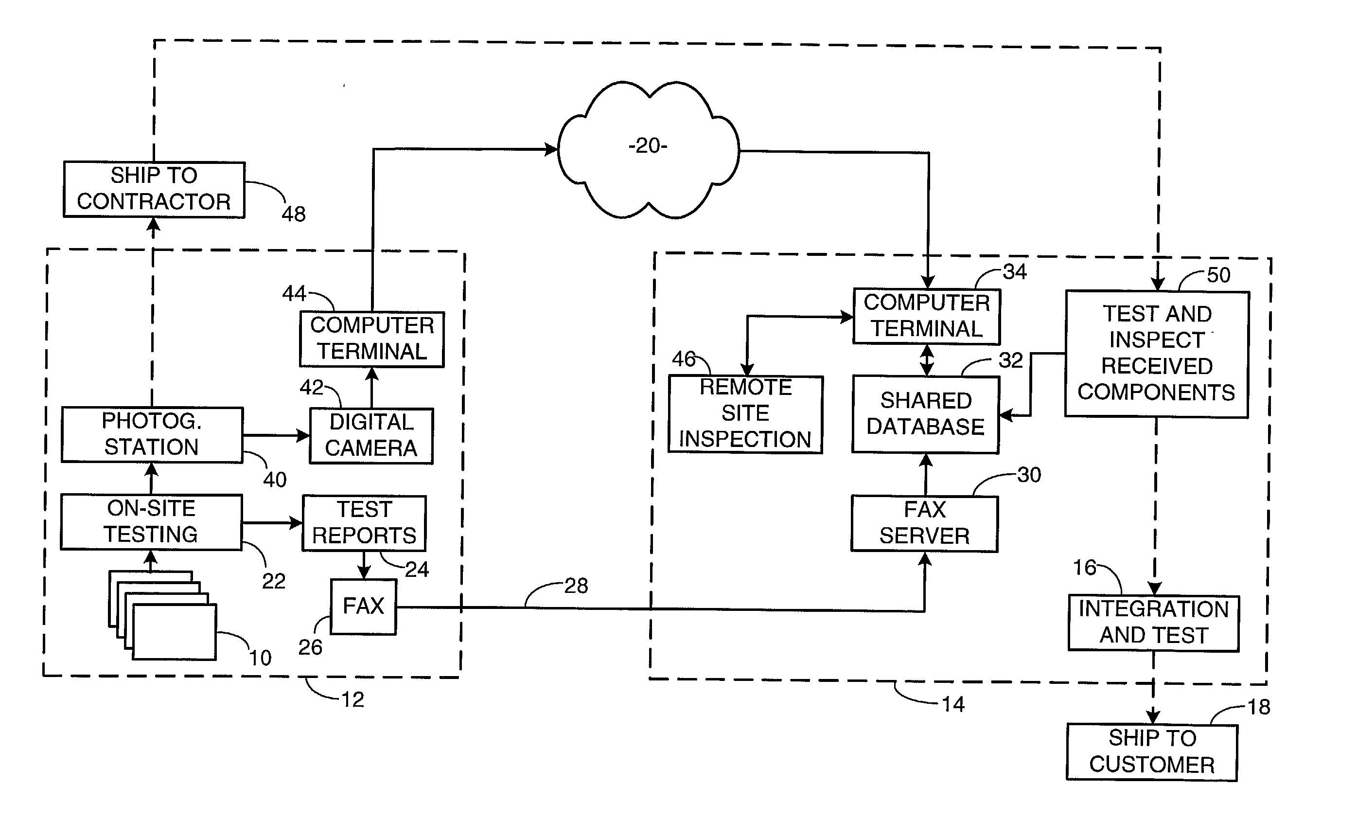
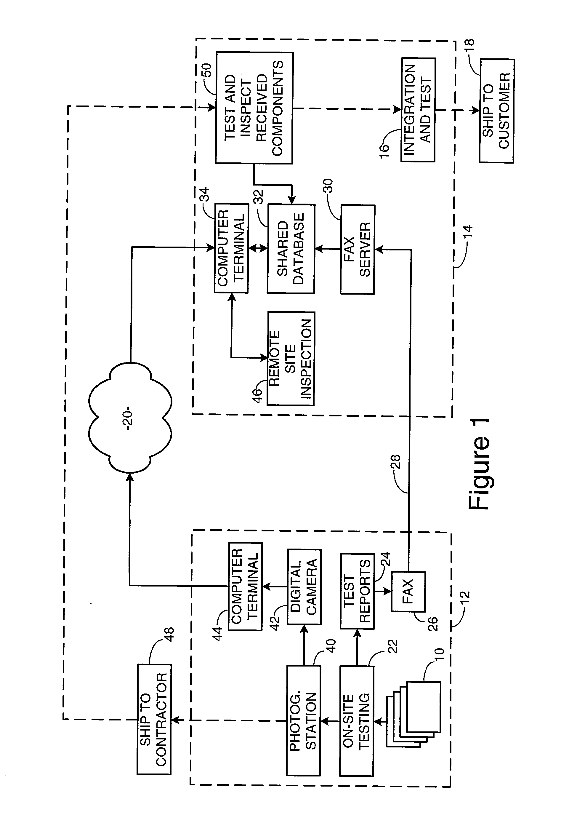
[0011] FIG. 1 is block diagram depicting the principal elements of an inspection process in accordance with the present invention;

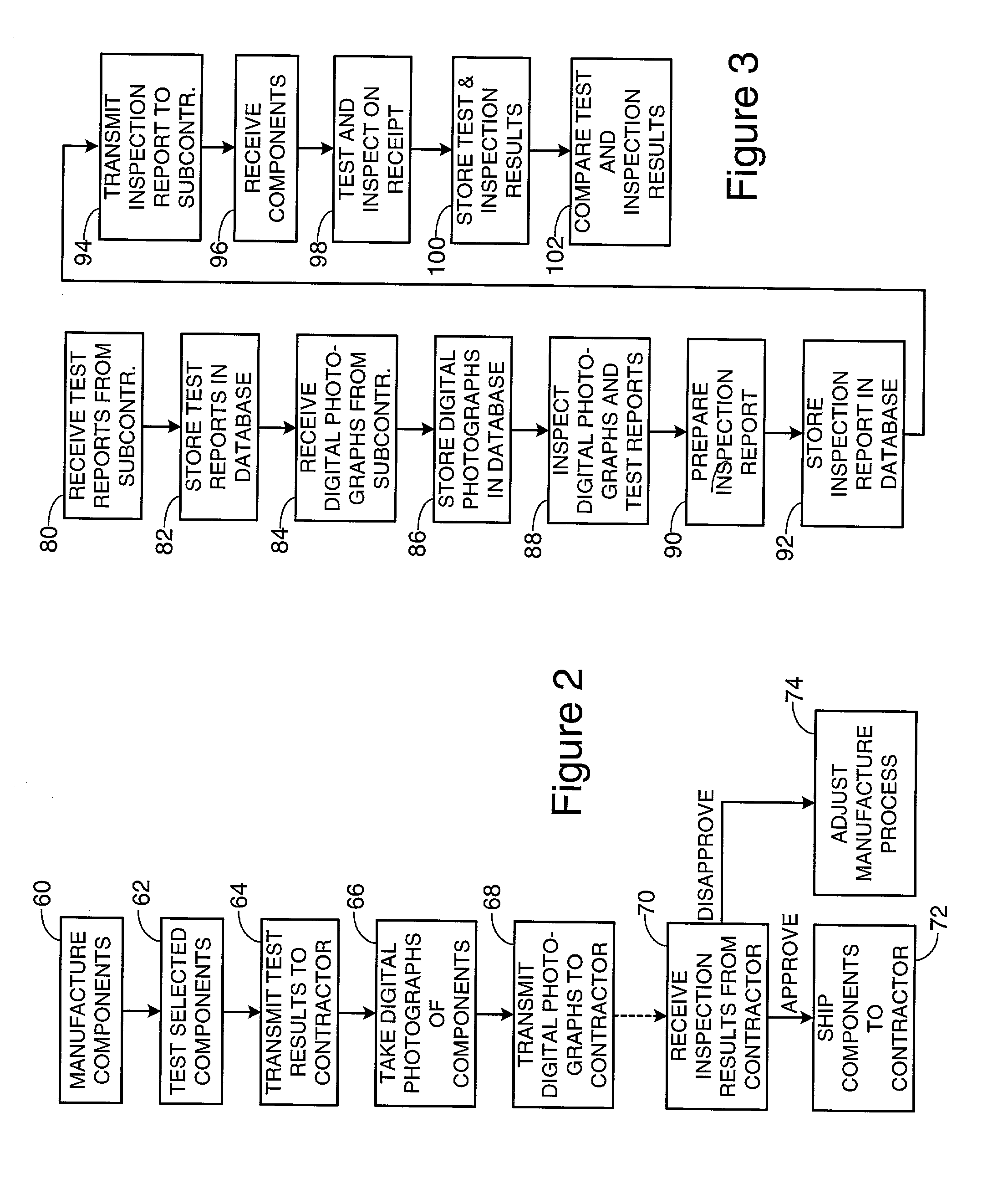
[0012] FIG. 2 is a flowchart depicting the principal steps performed at a manufacturing site in accordance with the present invention; and

[0013] FIG. 3 is a flowchart depicting the principal steps performed at a contractor site in accordance with the present invention.

DESCRIPTION OF THE PREFERRED EMBODIMENT OF THE INVENTION

[0014] As shown in the drawings for purposes of illustration, the present invention pertains to a novel method for performing inspections of manufactured components at their points of manufacture or assembly. In the past, components intended for shipment to another site, usually for integration into a larger structure or system, were inspected at the source site by inspectors who traveled there specifically for the inspections. This procedure not only incurred a significant travel co...


PUM


Abstract

A method for verifying the quality of manufactured components by conducting manufacturing site inspections of components remotely from another site, such as a component integration site. Selected components are physically tested and digitally photographed at the manufacturing site and the resulting test reports and digital photographs are electronically transmitted to the other site. An inspector views the test reports and digital photographs, then generates an inspection report for transmission back to the manufacturing site. Upon receipt of approval of the tested and photographed components, personnel at the manufacturing site ship the components. Component inspectors are relieved of the burden of traveling to manufacturing sites and manufacturers do not have to delay shipment or further production while waiting for a physical inspection of components.

Description

[0001] 1. Field of the Invention[0002] This invention relates generally to techniques for inspecting manufactured components at the point of source of the components. Complex manufactured apparatus and systems typically include components made by multiple manufacturers, often in different geographical locations. It is highly desirable, and in many cases mandated by contract or government regulation, that manufactured components be inspected at their source of manufacture or assembly, to ensure compliance with technical and quality specifications.[0003] 2. Prior Art[0004] In the past, source inspection of components has required the physical presence of a qualified inspector, who performs inspections using appropriate precision equipment at the manufacturing site. In many cases, the inspector uses an optical microscope to examine each manufactured component, or a selected percentage of manufactured components of the same type. The inspector is usually an employee or agent of a contra...

Claims


Application Information

Patent Timeline
Patent Type & Authority Applications(United States)
IPC IPC(8): G06Q10/06
CPCG06Q10/06
Inventor WILSON, ETHEL M.RADFORD, EDWARD A. JR.
Owner NORTHROP GRUMAN CORP
Learn More