Kalman filter state estimation for a manufacturing system

a manufacturing system and filter state technology, applied in the field of kalman filter state estimation technique for monitoring a manufacturing system, can solve the problems of difficult and often impossible to obtain measurement of key process variables, difficult and often difficult tasks, and often confused measurements

Inactive Publication Date: 2004-06-29
ADVANCED MICRO DEVICES INC
View PDF14 Cites 142 Cited by
  • Summary
  • Abstract
  • Description
  • Claims
  • Application Information

AI Technical Summary

Problems solved by technology

Because of the nature of the process conditions and the high cost of materials, it is very difficult and often impossible to obtain measurements of key process variables while the process is operating.
This task is made more difficult by the fact that measurements are often confounded by several different possible sources of variation.
The manufacture of semiconductor devices is characterized by expensive equipment and raw materials being used to create microscopic features in a batch processing environment.
These conditions ultimately mean that it is difficult (and in many cases impossible) to measure important quality variables in situ.
Unfortunately, it is typically not possible to go back and perform an operation again to correct a misprocessed batch.
As a result, aggressive control laws must be chosen because the manufacturing constraints do not allow a series of off-target batches while the controller approaches the target.
When the system model is able to make accurate predictions, the controller can be quite aggressive.
A controller that is too aggressive in the presence of model error and other uncertainties can actually exhibit poor performance and may lead to instability.
On the other hand, larger, more dramatic changes can upset the process by introducing dynamics more quickly than the process can handle.
In many practical applications, it is not feasible to obtain an exact model form for the process under study.
So, online system identification often takes the form of a parameter estimation problem.
However, real processes and the disturbances to them change over time, so it is not necessarily true that all process variables of interest will remain stationary.
In addition, there are many systems where all of the measurements important to control cannot be taken as frequently as desired.
In this context, static limits on process variables do not always make sense.
The optimal control problem is to determine the set of inputs that minimize (or maximize) an objective function while satisfying the constraints of the system model and any additional process requirements.
For most real processes, the above problem often results in a set of nonlinear differential equations with mixed boundary conditions.
This is because the true model of the system is often either unknown or too complicated for the optimal controller to have a closed form solution.
The main limitation of an offline system identification scheme is that it cannot predict how the model may change in the future.
Process changes appear as errors in the values of the model parameters.
Identification of a process under automatic control is complicated because the actions of the controller mask the underlying behavior of the process.
A difficulty arises because the satisfaction of a typical control objective lowers the amount of excitation as the process reaches a steady state at the desired operating point.
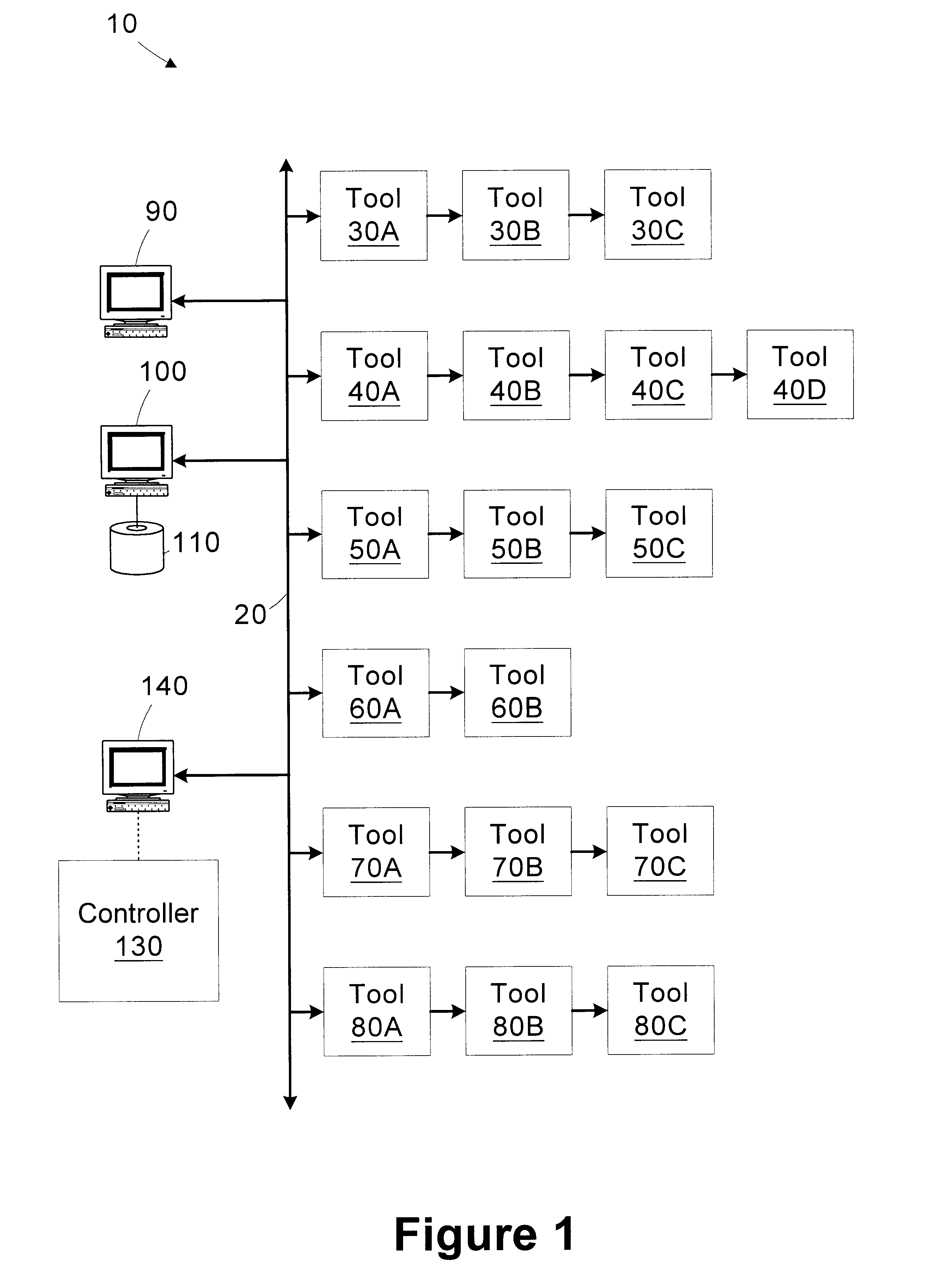
Run-to-run batch control in semiconductor manufacturing is often complicated by having multiple products and multiple processing tools.
These situations arise very often in semiconductor manufacturing, but they are also an issue in other batch processing environments, such as the production of polymers.
It is important that each batch meet its required specifications, but it is difficult to choose appropriate recipe settings when switching between different products and tools.
However, the rate can drift from batch to batch, even if only one product is being made.
This can be caused by reactor fouling, degradation of consumable materials, or process leaks.
Simply tracking an estimate for r from run to run is not acceptable because each switch to a different product appears as a step change.
Reactor fouling causes the rate to continually decay over the course of the runs.
However, in a real manufacturing environment, several complications arise.
For example, there can be several processing tools, new products appear, and experiments can be very expensive in terms of both raw materials and processing tool downtime.
The impact here is that the product specific factors are not always known a priori, so it is not necessarily safe to assume k.sub.p (and hence C) are known values.
This technique, while simple to understand, is limited because it is a rule-based scheme that relies on concepts that are difficult to quantify.
Furthermore, it is not always possible to solve the model equations for each parameter in turn.
It is easier to learn about the process by making large input changes or running non-production experiments, but this directly opposes the primary goal of the controller.
Run-to-run control as practiced in high-volume multi-product semiconductor manufacturing does not easily fit into the framework of traditional approaches to process control.
One reason this approach is not always successful is that there are often multiple processing tools as well as multiple products.
It is a common practice in today's microelectronics manufacturing facilities to have many different products and processes run on each processing tool, mainly because of the high capital costs associated with the tools and the limited capacity of the facility.
Determining how to do controller updates in this environment can be a challenging task.
When the various processes run on the tool are significantly different, the controller may behave unexpectedly because a change to a new process can appear to be a large disturbance.
In addition, it may take several successive runs of a given process for the controller to stabilize, but manufacturing constraints may prevent this from happening.
One very difficult task in this situation is determining which of the many possibilities (parameters, bias estimates) is the source of the observed errors in the output.

Method used


Image

  • Kalman filter state estimation for a manufacturing system
  • Kalman filter state estimation for a manufacturing system
  • Kalman filter state estimation for a manufacturing system

Examples


Embodiment Construction

Illustrative embodiments of the invention are described below. In the interest of clarity, not all features of an actual implementation are described in this specification. It will of course be appreciated that in the development of any such actual embodiment, numerous implementation-specific decisions must be made to achieve the developers' specific goals, such as compliance with system-related and business-related constraints, which will vary from one implementation to another. Moreover, it will be appreciated that such a development effort might be complex and time-consuming, but would nevertheless be a routine undertaking for those of ordinary skill in the art having the benefit of this disclosure.

Referring to FIG. 1, a simplified block diagram of an illustrative manufacturing system 10 is provided. In the illustrated embodiment, the manufacturing system 10 is adapted to fabricate semiconductor devices. Although the invention is described as it may be implemented in a semiconduc...


PUM


Abstract

A method for monitoring a manufacturing system includes defining a plurality of observed states associated with the manufacturing system. State estimates are generated for the observed states. An uncertainty value is generated for each of the state estimates. Measurement data associated with an entity in the manufacturing system is received. The state estimates are updated based on the measurement data and the uncertainty values associated with the state estimates. A system for monitoring a manufacturing system includes a controller configured to define a plurality of observed states associated with the manufacturing system, generate state estimates for the observed states, generate an uncertainty value for each of the state estimates, receive measurement data associated with an entity in the manufacturing system, and update the state estimates based on the measurement data and the uncertainty values associated with the state estimates.

Description

1. Field of the InventionThis invention relates generally to the field of semiconductor device manufacturing and, more particularly, to a Kalman filter state estimation technique for monitoring a manufacturing system.2. Description of the Related ArtIt is typical in semiconductor manufacturing to see many different products being made by using a variety of process conditions on the same pieces of equipment. Because of the nature of the process conditions and the high cost of materials, it is very difficult and often impossible to obtain measurements of key process variables while the process is operating. Product wafers are run in batches on processing tools using recipes, which specify the parameters necessary to run the tool such as pressure, temperature, and processing time. Measurements are made after processing steps are completed to determine if batches meet their specifications. Run-to-run control methods use the measurement data available at the end of each run to determine ...

Claims


Application Information

Patent Timeline
Patent Type & Authority Patents(United States)
IPC IPC(8): G05B13/02G06F19/00G05B13/04G05B23/02
CPCG05B13/04G05B23/0254
Inventor PASADYN, ALEXANDER J.
Owner ADVANCED MICRO DEVICES INC
Why Eureka
Try Eureka