Automated manufacturing control system

a manufacturing control and automatic technology, applied in the field of industrial automation, can solve the problems of large flat area, inability to apply barcode labels on raw materials, and inability to meet the requirements of outgoing production, and achieve the goal of complete automation of reading operations

Inactive Publication Date: 2006-06-27
COGISCAN
View PDF34 Cites 147 Cited by
  • Summary
  • Abstract
  • Description
  • Claims
  • Application Information

AI Technical Summary

Benefits of technology

[0042]In accordance with a more specific aspect of the present invention, there is provided a system which greatly reduces the human interaction relative t

Problems solved by technology

All these elements will have to be prepared and, if an error occurs and a wrong element is used or the wrong information about it is entered, the outgoing production will not conform to the specifications.
This yields an inventory that relies highly on human interventions and that is always outdated as it is not in real-time.Process control.
One general drawback of using barcodes is the need of a sufficiently large flat area to apply a barcode label which is not always available on raw material, its container, or other parts to be traced.
This can be a major restriction toward complete

Method used


Image

  • Automated manufacturing control system
  • Automated manufacturing control system
  • Automated manufacturing control system

Examples


1st example

1st Example

Transponders on Reels and Trays

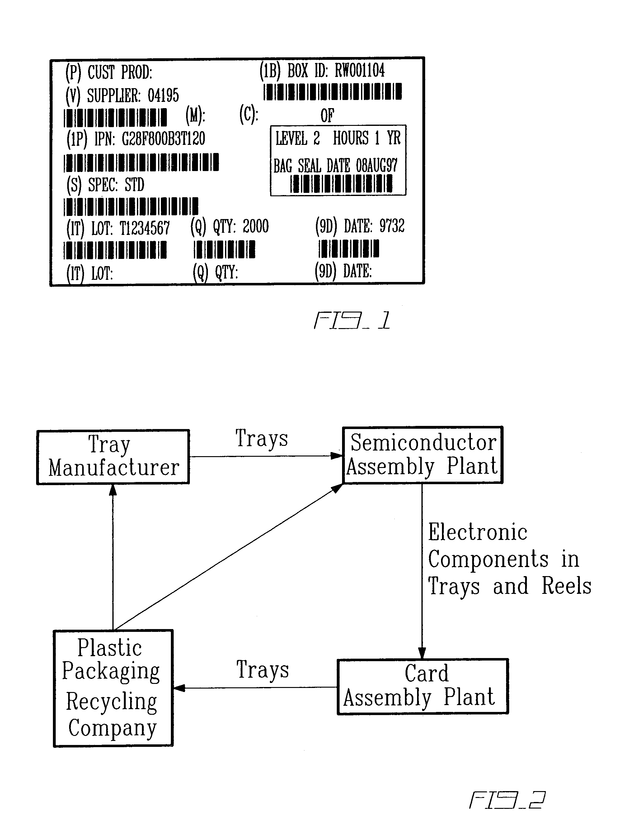
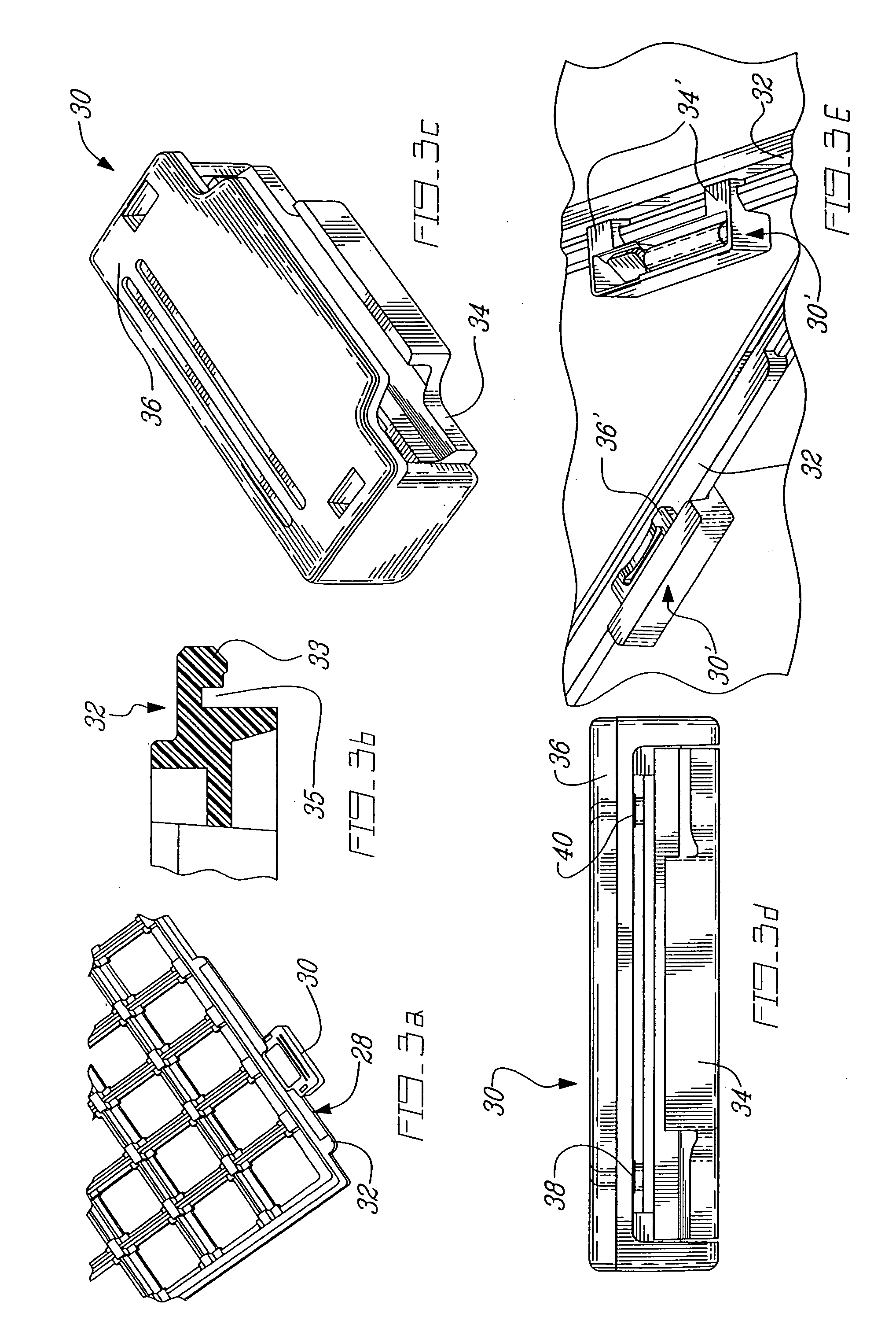
[0083]Given the existing infrastructure of barcode identification and the relatively high unit cost of a typical transponder, the present example is based on the use of a temporary means to attach the transponder, with different designs adapted to each format of packaging. In this case, the transponders 12 (i.e. the chip and the coupling element) are used in a closed loop cycle. For this reason, the benefits of the system must be more important that the additional cost associated with the attachment and removal of the transponders 12, including the initial data entry. Any application would become even more advantageous if the card assembly plant can receive the reels and trays (FIGS. 3a and 3f) from its suppliers with the transponders 12 already attached thereto and with the data already present in the proper format.

[0084]In this application, it is important that the shape and location of the transponders 12 do not affect the normal handling...


PUM


Abstract

An automated manufacturing control system is proposed to greatly reduce the human interaction relative to the data transfer, physical verification and process control associated with the movement of components, tooling and operators in a manufacturing system. This is achieved by the use of data carriers which are attached to the object(s) to be traced. These data carriers (12) can store all the relevant identification, material and production data to required by the various elements, e.g. stations, of the manufacturing system. Various readers, integrated with controllers and application software, are located at strategic points of the production area, including production machines and storage areas, to enable automatic data transfer and physical verification that the right material is at the right place at the right time, using the right tooling.

Description

FIELD OF THE INVENTION[0001]The present invention relates to industrial automation and, more particularly, to a system and method for controlling and monitoring a manufacturing process.BACKGROUND OF THE INVENTION[0002]In a manufacturing system, in order to deliver the finished goods, a lot of elements have to be moved on the production floor from time to time as they are required in different locations. Most of these movements require a manual intervention, although some of them may be automated using robots, conveyors or some other means. Along with these movements, the necessary information needs to follow. In most occasions, this information follows manually, although there exists some ways to partly automate this aspect that will be discussed hereinbelow. Here are examples of movements that can occur in a manufacturing system and the related data that needs to follow these movements;[0003]Machine set-up. In order to prepare a given machine to produce a given part, it needs to be...

Claims


Application Information

Patent Timeline
IPC IPC(8): G06F19/00G05B19/418
CPCG05B19/4183G05B19/41865G05B2219/31095G05B2219/49302G05B2219/33192G05B2219/33203G05B2219/32197Y02P90/02
Inventor MONETTE, FRANCOISCORRIVEAU, ANDREDUBOIS, VINCENT
Owner COGISCAN
Why Eureka
Try Eureka